2. Setup
Power requirement
The CS-3A Cell Stand is applicable for either 100 V or 240 V (50-60 Hz) power supply. Using power switching regulator, the Cell Stand can set up any place without any modification.
Power cord connection
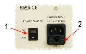
One should push the socketed end of the power cord into the port located in the back panel (See Fig. 2-1). After the connection, power switch should be "ON". This switch is labeled with a “O” and “|”. When in “O”position, the power is OFF and when in “|”, the power is ON. You make sure the power switch at the ON position. If there is any problem for the power ability, it is better to check the fuge whether it is properly installed. In any case, the fuge will be broken up if power overflows.
 |
| Figure 2-1. Power switch (1) and fuse folder under power cord connector (2) |
As shown in Fig. 2-1, the fuse is located under power control connector. Pull the fuse holder, and check whether it works or not. If it does not work, it should be replaced with new one.
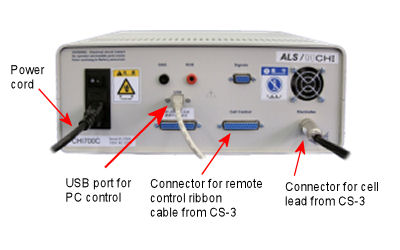
The CS-3A gas purge and stirring can be controlled by the ALS/CHI Electrochemical Analyzer. The control line is 25 pin cable (Cat No 010880 CPEE interface cable) between the remote connector on the rear of the Cell Stand and the cell stand connector on the rear panel of the ALS/CHI Models (See Fig. 2-2). The electrode leads are connected to the ALS/CHI Models by inserting cell connector on the end of the cell lead cable into the cell input connector on the rear panel of the ALS/CHI Models.
 |
| Figure 2-2. Connection of CS-3A to ALS/CHI Models |
Cell lead connection
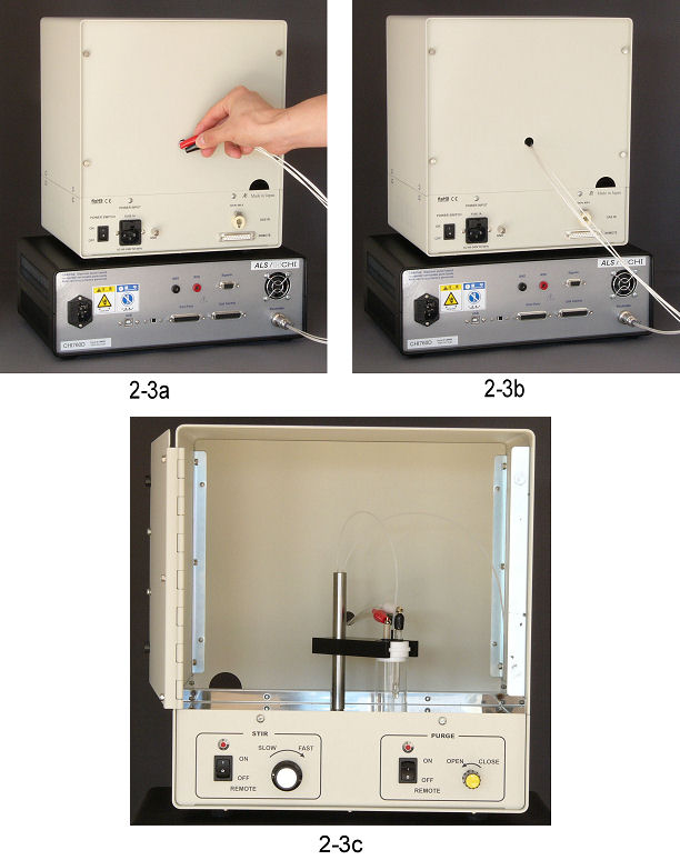
The cell leads are passed into rear panel of CS-3A Cell Stand, and see Fig. 2-3a to 2-3c. Each of aligator clip is passed through the hole carefully.
 |
| Figure 2-3. Cell lead connection from ALS/CHI Models 2-3a: Pass of the aligator clips through the hole of CS-3A 2-3b: Connection of electrode terminals with ALS/CHI Models 2-3c: Connection of the aligator clips to the electrodes in the Faraday cage of CS-3A |
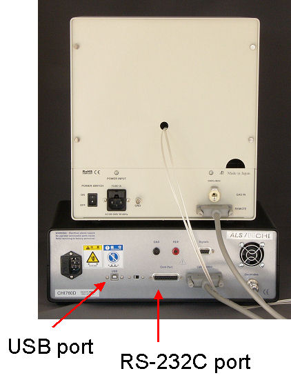
After passing the electrode leads and connecting the communication cable of USB or RS-232C with PC, the electrode leads and control line cable are connected between ALS/CHI Models and CS-3A Cell Stand.
 |
| Figure 2-4. PC ports from CS-3A |
![]()

