4. Operation
Cell top/test vial placement
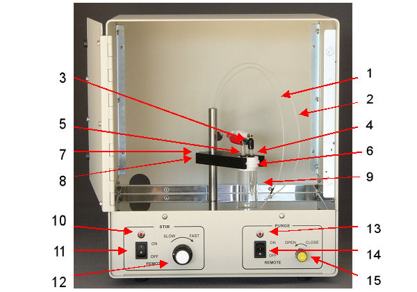
Cell top positioner is raised, the glass cell vial is placed under the teflon cell vial cap, and the cell top positioner is lowered onto the cell vial (Fig. 4-1). The cell vial cap snaps out of the cell top positioner for easy cleaning.
The teflon cell cap for CS-3A is fitted into the cell top positioner, and slided out of the positioner.
- Identification of the front panel components in CS-3A are (Fig. 4-1):
 |
| Figure 4-1. Front panel components in CS-3A |
1. Gas purge line for Test Sample
2. Gas blanket line
3. Working electrode (green clip)
4. Reference electrode (white clip)
5. Counter electrode (red clip)
6. Teflon cell vial cap
7. Cell top positioner
8. Thumb screw to control height adjustment
9. Test sample glass cell vial
10. Stir LED: LED is flashing when stir is turned on, either manually or remotely
11. Stir control switch: Manually control stirrer or select remote control option
12. Knowb to manually control stirring rate
13. Gas purge LED: LED is flashing when gas purge is turned on for test sample cell, either manually or remotely
14. Test sample gas purge control switch: Manually control gas purge in test sample cell or select for remote control
15. Test sample purge rate controller: Needle valve controlling gas flow rate to test sample gas dispersion tube
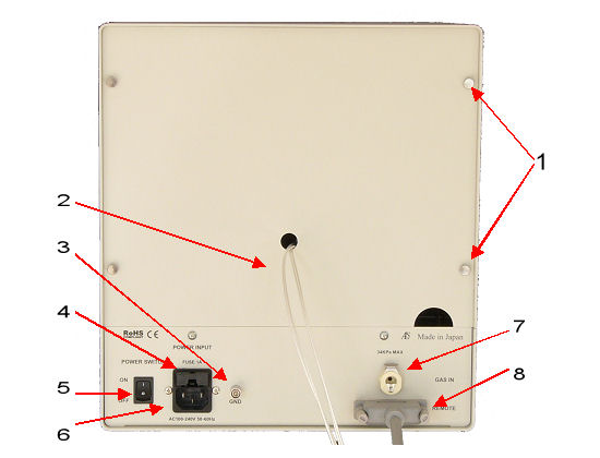
- Identification of the rear panel components are (Fig. 4-2):
 |
| Figure 4-2. Rear panel components in CS-3A |
1. Thumb screws: Four thumb screws for easy removal of back panel
2. Cell leads: Cell leads with connector for connection to electrode terminal of CHI instruments
3. Ground
4. Fuse holder
5. Power ON/OFF
6. Power cord: Socket for power cord. Make sure that the power cord is connected to a grounded outlet
7. Gas inlet connector: Bulkhead fitting providing connection to external gas source
NOTE: 35 kpa maximum pressure
8. Remote connector: 25 pin D connector for remote control by CHI instruments
Gas purge
- Test sample:
The flow rate of the gas, whether it is directed towards purging or blanketing the sample, is controlled by a front panel switch and knob (Fig. 4-1, No. 15 and 17). When it is toggled to the ON position, the gas flow is diverted to the purge tube and cannot be changed by REMOTE control. When switched to the OFF/REMOTE position, the gas is directed to the BLANKET tube. It must control PURGE via external control through the REMOTE connector on the rear panel (Fig. 4-2, No. 7). Without REMOTE control, thus, the ON position activates the PURGE line and the REMOTE position activates the blanket line. For REMOTE controls of the PURGE and BLANKET functions, the switch must be in the REMOTE position. The flow rate is controlled by rotating the knob labeled Test Sample. As counterclockwise rotation increases the flow, clockwise rotation decreases the flow to the cell. The LED is started to flashing when the purge function is switched on, manually or remotely.
- Stir:
The CS-3A Cell Stand has a magnetic stirrer built into the unit. The stirring functions ON, OFF and rate can be controlled by the front switches. The switch under the STIR label controls whether the stirrer is ON or OFF or controls remotely (Fig. 4-1, No. 12). The ON position overrides all other commands and turns the stirrer motor on. The REMOTE position is equivalent to OFF in manual operation but is the required position for turning on the stirrer by external (REMOTE) control. The rate of stirring is controlled by the knob directly to the right of the control. The “O” position is no stirring and the stir rate increases with an increase in the position number. The LED is flashing when the stir function is switched on, manually or remotely.


