Connection of SEC2020 and Potentiostat
Here, the SEC2020 Spectrometer connection with some potentiostat using trigger cable, which is one of the content of the system package, is introduced below.
Trigger mode measurement
The spectrometer supports Trigger Mode for synchronized measurement with external device. Depending on the trigger mode, you can control acquisition of spectrometer data with external Input/Output signal. It makes possible to control the spectrometer measurement with external operation of the external devices.
- Configuration
- Cable connection
- SEC-C setting
- Synchronized measurement
Configuration
The electrochemical measurement synchronized with a spectrum monitoring is introduced in this section.
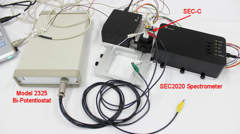
The electrochemical reaction is performed using Model 2325 Bi-Potentiostat (Cat. No. 013345), and the spectrum monitoring is performed using SEC2020 Spectrometer system.
The instruments and the respective accessories, and the reaction chamber, in this case the SEC-C Thin Layer Quartz Glass Spectroelectrochemical cell kit are listed below.
SEC2020 Spectrometer system
Model 2325 Bi-Potentiostat
| Catalog No. | Description | 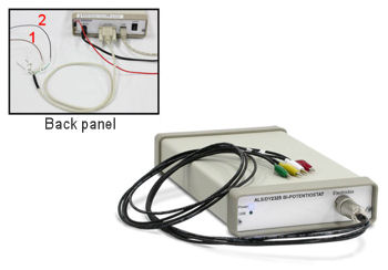
 |
| 013345 | Model 2325 Bi-Potentiostat | |
| 013349 | Model 2325 Software | |
| For the the connection to the SEC2020 Spectrometer system, the remote cable is used. The remote cable is included in the contents of the Model 2325 Bi-Potentiostat. |
||
Model 2325 Bi-Potentiostat (Cat. No. 013345) is used for the electrochemical measurement, for detailed information about the products, visit the web page for the Model 2325 Bi-Potentiostat (Cat. No. 013345).
SEC-C Thin Layer Quartz Glass Spectroelectrochemical cell kit
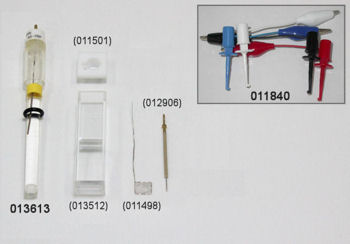
The SEC-C Pt Gauze working electrode (Cat. No. 011498) connector wire is a 0.5 mm of the diameter platinum wire, which makes it very delicate and fragile. For the set up IC clip (Cat. No. 011840) is used to do not connect the crocodile clip directly to the connection wire of the SEC-C Pt Gauze working electrode.
Cable connection
Trigger cable (SEC2020 Spectrometer system content) and Remote cable (included in the content of Model 2325 Bi-Potentiostat) are required for the connection.
- SEC2020 Spectrometer system
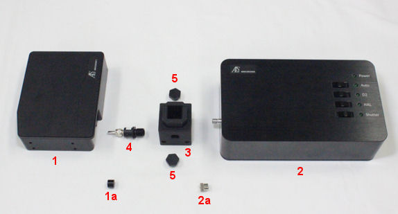

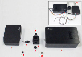
Fig. 1 Spectrometer system content.
(1) Spectrometer
(1a) Protector of the SMA 905 from the spectrometer
(2) Light source
(2a) Protector of the SMA 905 from the light source
(3) Cuvette holder
(4) Fiber collimator
(5) SMA905 adaptor for light shielding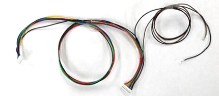

Fig. 2 Trigger cable from the content of the SEC2020 Spectrometer system, for the connection of the spectrometer to external device and light source.
Fig. 3 The free two wires (① Brown (Input (Trigger-IN)) and ② Black (Ground (GND)) are for the connection to the potentiostat. For this reason, the connector which has the free wires connected must be connected to the spectrometer.
- Model 2325 Bi-Potentiostat
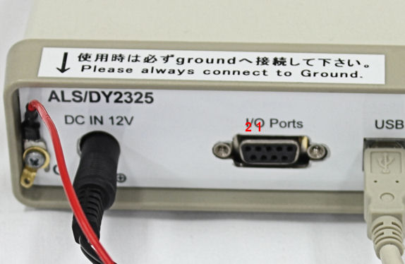 Fig. 4 Model 2325 Bi-Potentiostat back panel.
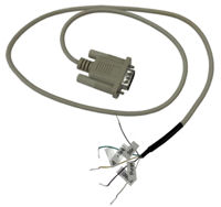

Fig. 5 Remote cable for the connection of the Model 2325 Bi-Potentiostat to SEC2020 Spectrometer system.Fig. 6 Connection using remote cable. ① (1) V_RDE cable (Analog ground of the instrument) and ② AGND cable (Voltage output (0 -10 V) that is proportional to RDE rotation speed of 0 – 10000 rpm. 50 ohm output.).
Connection of SEC2020 and Model 2325
SEC2020 Spectrometer system and Model 2325 Bi-Potentiostat setting separately in the previous section is connected as shown below.
Fig. 7 Connection of the SEC2020 Spectrometer system and Model 2325 Bi-Potentiostat.
| SEC2020 Spectrometer system | Model 2325 Bi-Potentiostat |
| ① Brown (Input (Trigger-IN) |
① V_RDE cable (Voltage output (0 -10 V) that is proportional to RDE rotation speed of 0 – 10000 rpm. 50 ohm output.) |
| ② Black (Ground (GND)) |
② AGND cable (Analog ground of the instrument) |
SEC-C setting and connection
SEC-C Thin Layer Quartz Glass Spectroelectrochemical cell kit (Pt) (Cat. No. 013510) is used for the spectroelectrochemical measurement.
For the set up special care for the connection of the working electrode is necessary. In the below connection IC clip for printed electrodes (Cat. No. 011840) is connected to the crocodile clip.
Cell preparation for Spectrometry
Set up of the spectrometer and cuvette is showed below with some "hints".
For the SEC-C Thin Layer Quartz Glass Spectroelectrochemical cell kit (Cat. No. 013510) setting, first set the working electrode and counter electrode into the SEC-C Teflon cap, and then fit to the SEC-C Thin Layer Quartz Glass cell with the sample to be measured, and last set the reference electrode.
Make sure that the SEC-C Pt Gauze working electrode (Cat. No. 011498) is clean. If not, polish with 0.05 um polishing alumina (Cat. No. 012620) by soft touch using cotton swab, and rinse with distilled water.
For the spectrum measurement, when taking the reference and dark spectrum, do not forget to save both spectrum. The saved spectrum can be used for the subsequent measurement.
After take and save the reference and dark spectrum, SEC2020 Spectrometer system is ready for the target sample measurement.
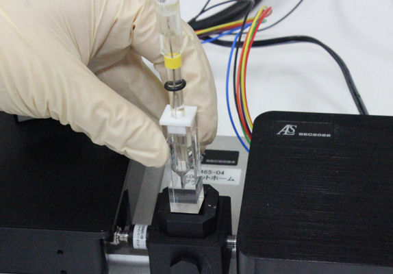 Fig. 8 For absorbance measurement, as a measurement sample, 2 mM potassium ferrocyanide/1 M KNO3 aqueous solution is used.
For the differential absorption spectrum measurement, the spectrum of the sample before measurement is taking as a reference spectrum.
Setting of the cell cable
It is not recommended to clip the SEC-C Pt Gauze working electrode directly, because the connection wire is very thin and it will bend easily.
For the set up below IC clip for printed electrodes (Cat. No. 011840) is used between working electrode and cell cable.
For the connection of the working electrode, take attention to do not clip in the insulated side.
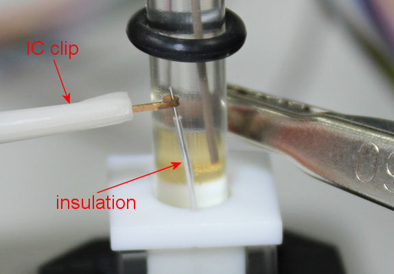 Fig. 9 Interface 1010E Potentiostat/Galvanostat/ZRA cell cable connection using IC clip. The connection must be in the exposed wire of SEC-C Pt Gauze working electrode, without the insulation.
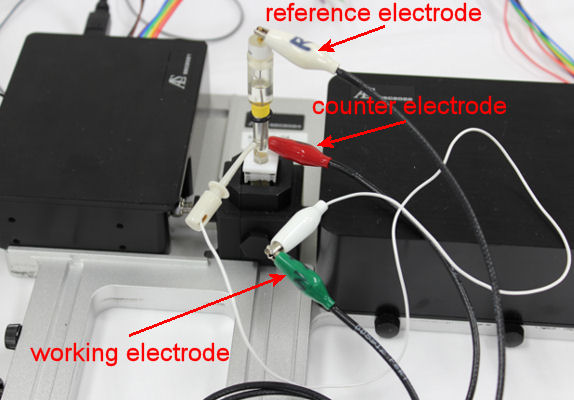 Fig. 10 IC clip is used between the crocodile clip of the Model 2325 Bi-Potentiostat cell cable and exposed wire from the SEC-C Pt Gauze working electrode.
Set up of the devices - SEC020 Spectrometer system and Model 2325
After finished the set up of the devices and the sample for the measurement is setting in the cuvette holder, the set up for the trigger measurement can be started.
For the spectrometry measurement the absorbance time sequence acquisition will be performed together with the cyclic voltammetry.
Spectra Smart (SEC2020 Spectrometer system)
Light source trigger
SpectraSmart can control the on/off states of an external light source via I/O signals.
Light source frame can be displayed on the right edge, where makes possible to control the type of the light, light on/off and shutter open/close.
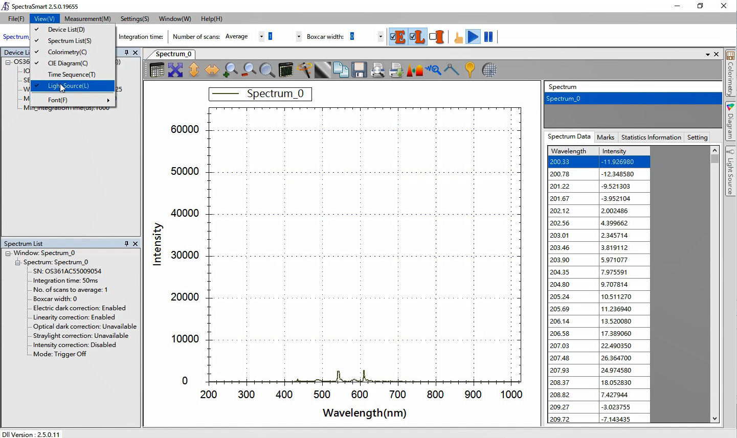

Fig. 11 For the set up of the light source control by the software, first select the menu bar View and choose Light source to show the light source frame on the right edge of the window.
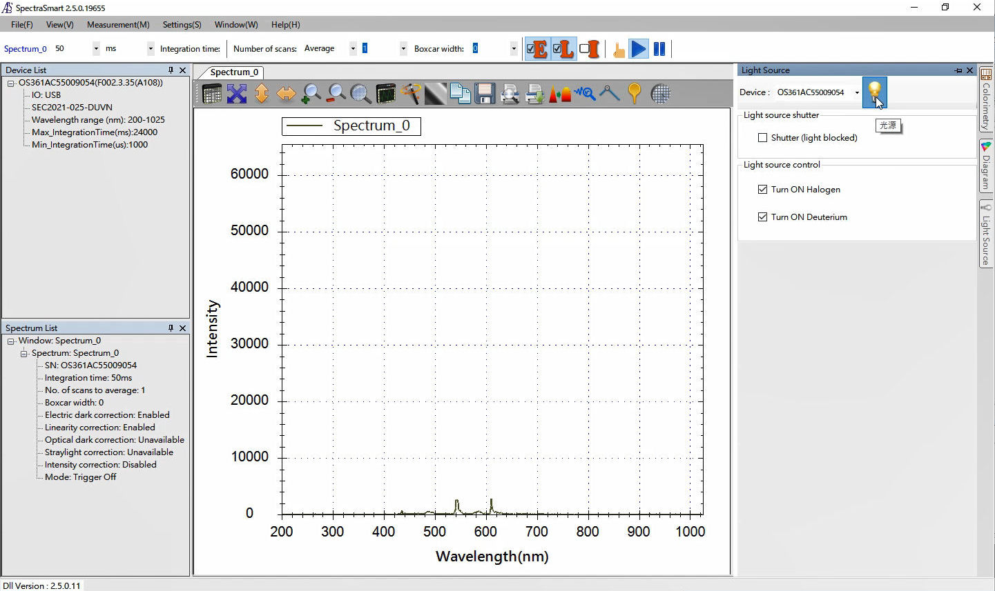

Fig. 12 Pressing the lamp at the light source frame, the operation mode is activated or inactivated.
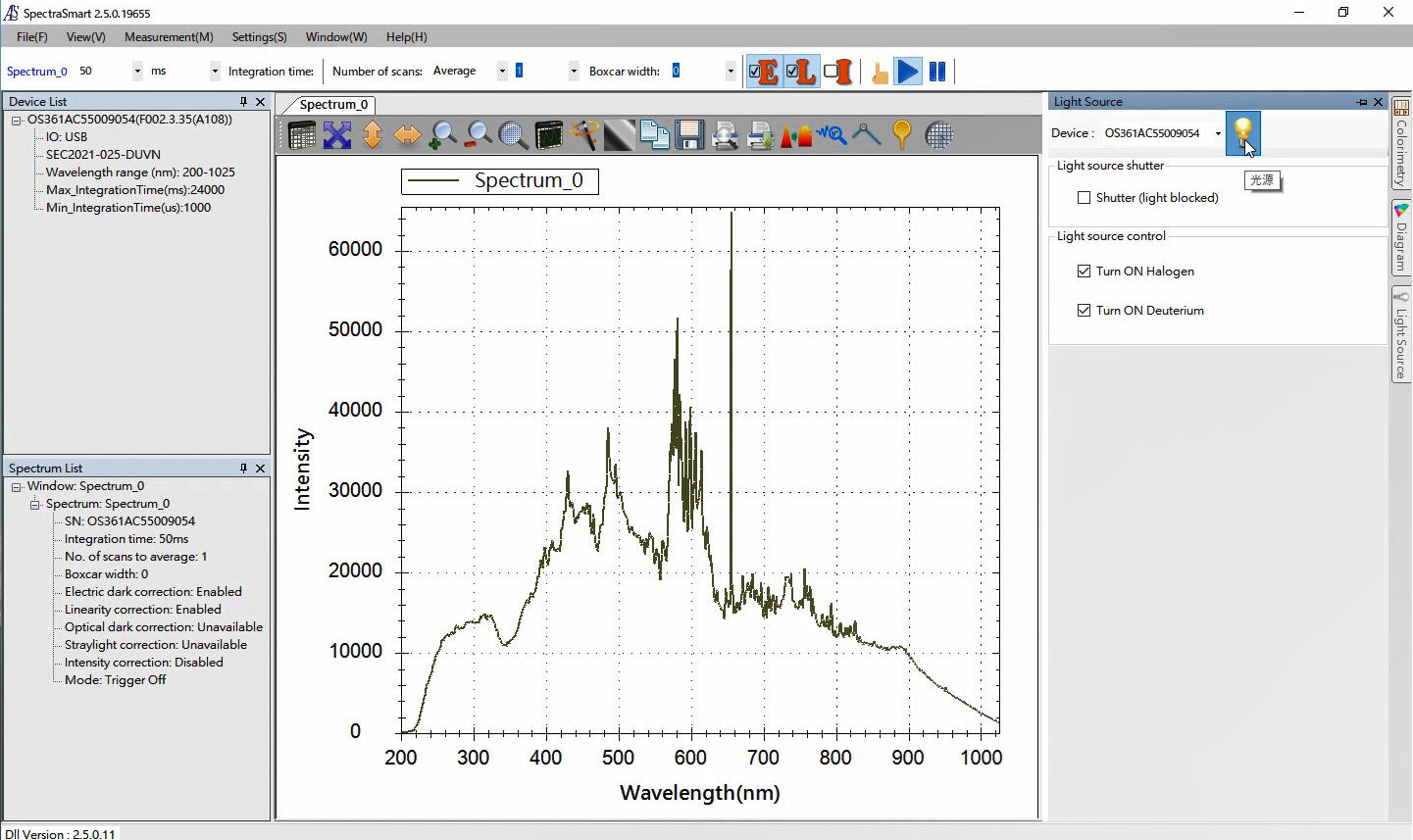

Fig. 13 After activated the light source operation, the lights are turned on. Also you can control the shutter to take the dark spectrum.
Reference and Dark spectrum
For the reference and dark spectrum, the data is taking for the set up Fig. 8 with distilled water.
Below, the reference and dark spectrum taking and saving step are explained in detail.
1. Setting Reference and Dark Spectrum
Before setting the test sample, take the reference and dark spectrum.
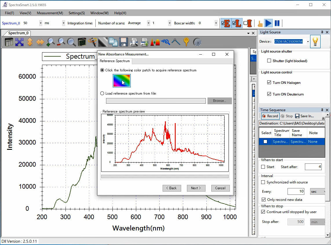

Fig. 14 Acquire the reference spectrum, which can be acquired the live spectrum, or can be read the previously acquired and saved, using the Browse button.
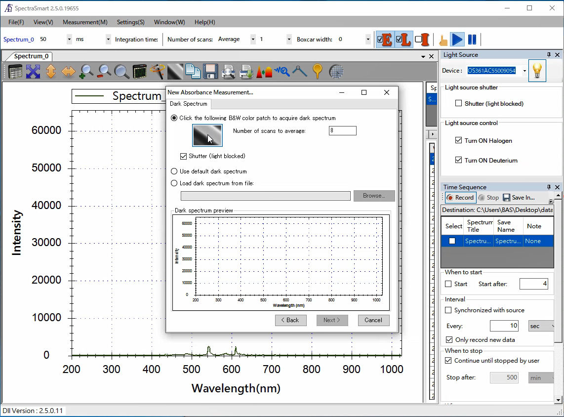

Fig. 15 Acquire the dark spectrum, closing the shutter (check the box, which is active when the light source trigger is used), or can be read the previously acquired and saved, using the Browse button.
2. Saving Reference and Dark Spectrum
Saving the reference and dark spectrum, they can be used for the subsequent measurement. Also, choosing the reference and dark spectrum, it is possible to save both in the same time.
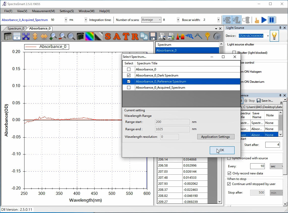

Fig. 16 Saving the reference and dark spectrum. It makes possible to use in a subsequent measurement.
Adjustment the X and Y scale
Adjust the X and Y scale, for the best visualization of spectrum to be measured.
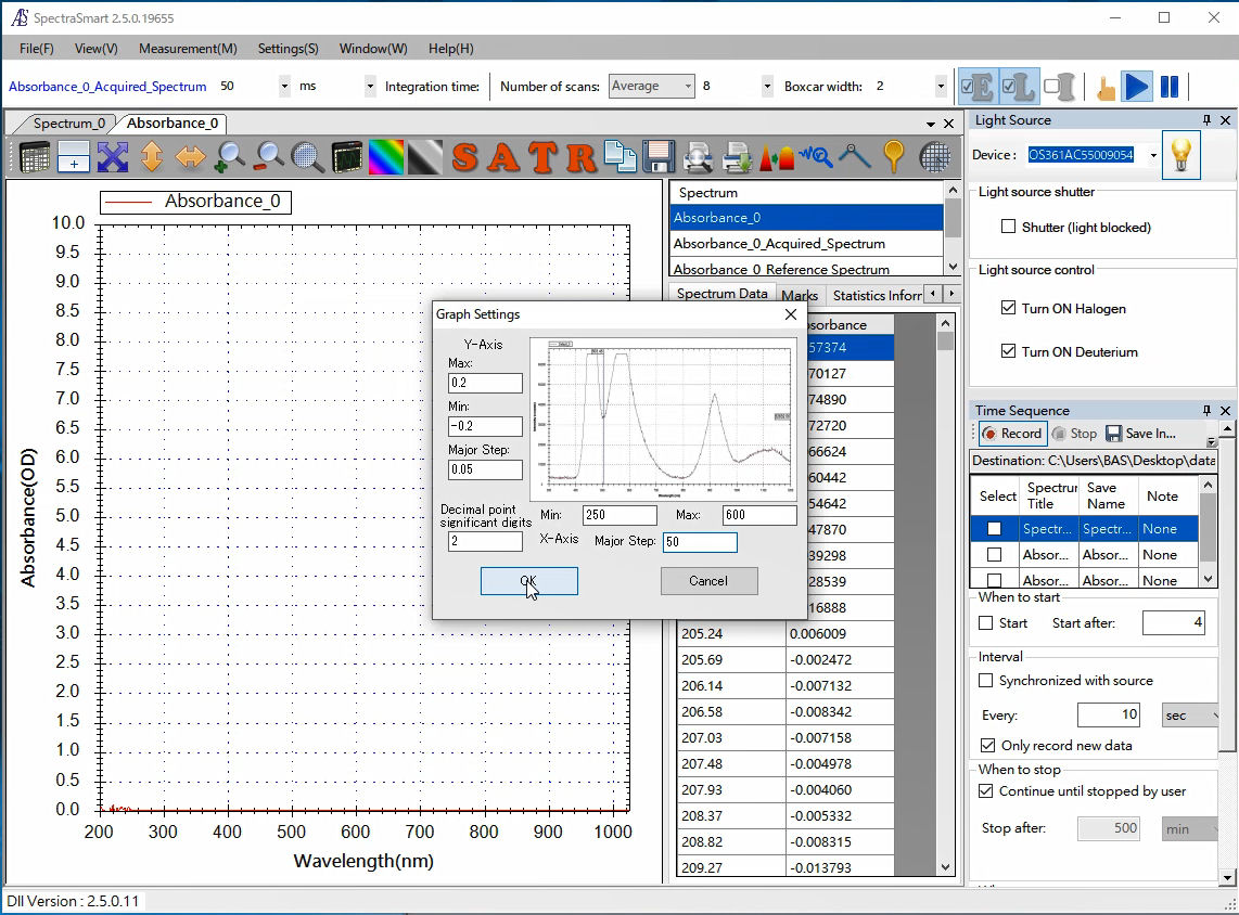

Fig. 17 Entry the scale range for the adjustment for the spectrum visualization.
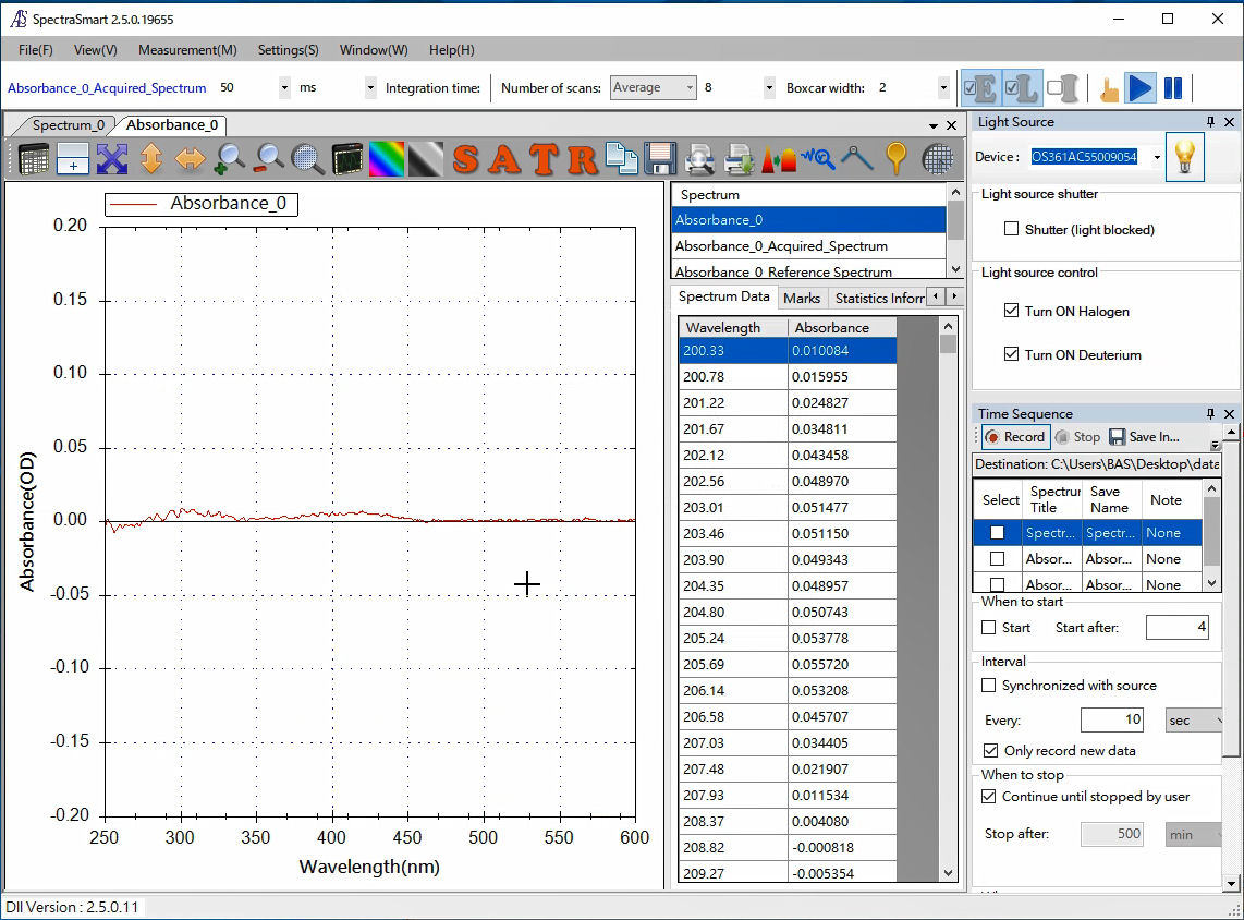

Fig. 18 Spectrum after adjusted the X and Y scale to be visualized.
Trigger setting
1. SEC2020 Spectrometer system (SpectraSmart)
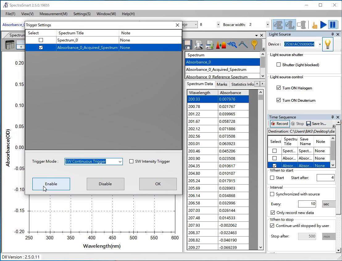
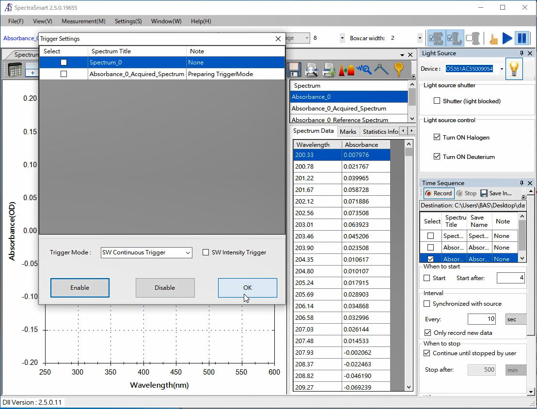
Set the trigger mode in the SEC2021 Spectrometer.
Saving the data
For monitoring the changes in the absorbance during the electrochemical measurement, the Time Sequence function can be useful.
Select Time Sequence button on the right vertical of the SpectraSmart window, the Time Sequence window opens on the right side, where the record condition can be setting.
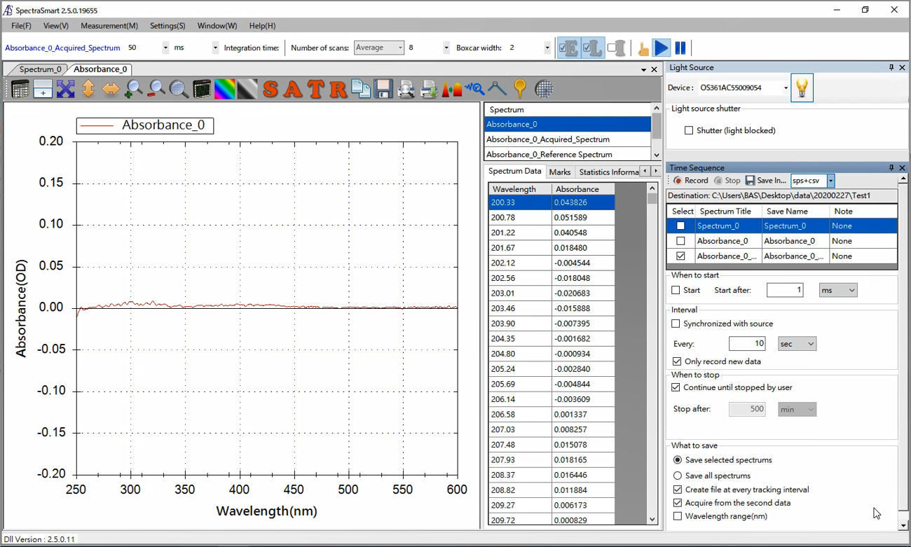

Fig. 21 Time sequence setting window for the setting of the data record condition. Also specify the folder to save the recorded data and the file format.
For the measurement introduced here, the Time Sequence function is chosen to save the absorbance spectrum data, and for the file format .sps (SpectraSmart’s proprietary file format) and CSV format are choose.
Model 2325 Software
Set the EC parameters and the trigger out of Model 2325 Bi-Potentiostat software.
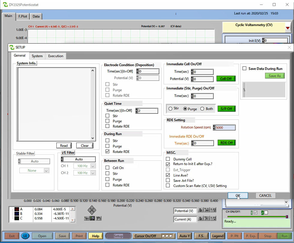

Fig. 22 For the synchronized measurement, set the trigger out of Model 2325. In the SETUP window, configure Rotation Speed (pm) to 5000 on the RDE Setting.
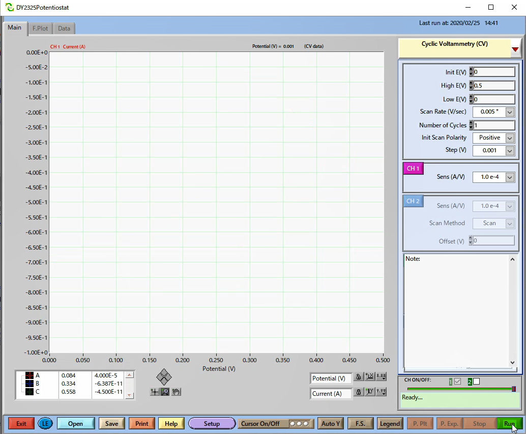

Fig. 23 Choose the technique and set the parameters. Here, Cyclic Voltammetry (CV) is selected.
The cyclic voltammetry is saved in the Framework data folder, and the spectrum data can be saved in the specified folder and filename.
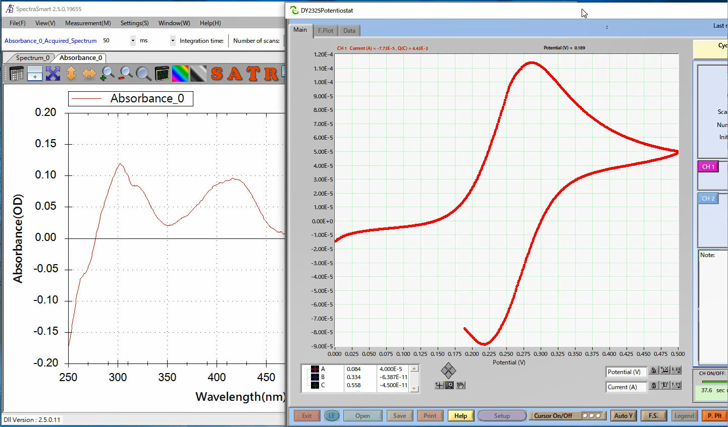
Cyclic voltammetry and absorbance spectrum
During measurement
When the measurement starts, it is possible to observe the spectrum change during the oxi-reduction reaction.
Data analysis
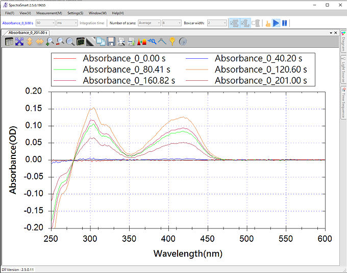
Saving the data in SpectraSmart’s proprietary file format (.sps), the overlay of the spectrum is possible, which makes possible to compare the spectrum data obtained in the measurement.
For the explanation example, the sampling time was setting to 10 ms, however for the data analysis, the data for 40 ms interval were selected and plotted in the same window.


