Chapter III - Optically Transparent electrode (Part 2)
This article will continue to introduce Hg-Pt, carbon film transparent electrode, metal grid electrode, porous glassy carbon electrode and porous metal electrode, and thin film grid electrode (Pt, Au, C).
1. Hg-Pt and carbon film optical transparent electrode
1.1 Hg-Pt film electrode - Expanding the cathodic potential region of the electrode
Sometimes, in order to expand the cathodic potential area of the electrode, electrochemical reduction of mercury ions on the surface of the Pt film optically transparent electrode can be used to form a thin mercury surface by electroplating, which increases the available cathodic potential range (about 300-400 mV negative shift) due to the large overpotential of hydrogen discharging on the surface of the mercury. By limiting the amount of deposited mercury a certain amount of light transmission can be retained. The mercury film is generally about 50 angstroms thick, and even thicker it will form mercury droplets.
This mercury-plated electrode allows the optical monitoring of metal deposition on the mercury film electrode and electrode reactions involving the loss of mercury from the electrode, in addition to the study of electrode reactions with negative potentials.
1.2 Carbon film electrode
Carbon film electrodes can be prepared by vacuum deposited carbon films on a quartz glass or germanium substrate. If the substrate is heated to 450 degrees before deposition, a better electrode can be obtained3-1). The thickness of the film is 280 - 310 angstroms. This electrode presents a larger resistance compared to the metal film electrode. In addition, its electrochemical properties are similar to those of the usual graphite electrodes. The carbon film optically transparent electrode on a quartz substrate has good light transmission in the entire ultraviolet-visible light range.
2. Metal grid electrode
In 1967, R. W. Murray et al. reported a use of a simple metal grid optically transparent electrode to observe the electrolysis process and the spectral changes of the electrochemical cell after the reactants were completely consumed3-2) - 3-4). The metal grid electrode used was a very fine metal micro grid prepared by an electrochemical deposition step shown in Figure 3-1. The 1000 mesh Au micro mesh optically transparent electrode was used in a thin layer electrochemical cell for spectroelectrochemical measurements. The light transmittance of the 1000 mesh Au micro-mesh used is about 45%, and the mesh is 17.6 µm (the light transmittance of 500 mesh is 60%, the mesh is 39 um, the light transmittance of 2000 mesh is 22%, and the mesh is 6.3 µm). The size of the Au micro mesh electrode in the figure is 1 x 3 cm. The micro mesh was sandwiched between two pieces of glass or quartz glass, each of which was previously coated with adhesive around its perimeter. A narrow strip (at the thick black line) was used as a spacer and bonded with moderate pressure. Then a generous amount of adhesive is applied to the edges of the sandwich sheets to ensure a tight seal and placed in a dry place to dry for a period of time before use. The bottom opening of the thin layer cell allows contact with the specimen solution, reference electrode and auxiliary electrode. The electrodes are connected at the conductive end of the electrode at B. The electrode is now designed for easy replacement of the internal solution, which is characteristic of the spectroelectrochemical flow cells used today. Using this thin layer cell, measurements of spectral changes during the oxidation of 3,3'-dimethylbenzidine were successfully performed. The time course of the absorption variation at 438nm was recorded.
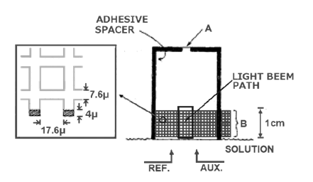
Fig. 3-1 Optically transparent electrochemical cell using gold grid electrodes3-2)
(The left side shows the size of 1000 mesh Au grid).
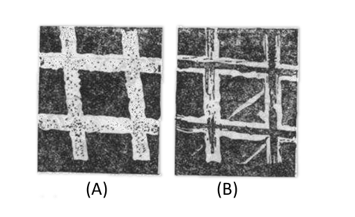
Fig. 3-2 Scanning electron microscope photograph of 500-lpi gold mesh grid (x 1000x)
(A) Dark side (B) Glossy side3-6)
The advantage of metal grid electrode is that it serves as an electrode with very good conductivity, and at the same time has high light transmittance and an unrestricted spectral range. Fig. 3-2 shows a scanning electron microscope photo of a gold grid with a bright surface near the original grating during electrodeposition. Pt grid is not suitable for preparation by electroplating and requires the use of coarsely woven Pt grid3-5). The light transmittance of the grid is due to the micropores in the metal, the metal framework is non-transmissive and the light transmission remains essentially constant throughout the UV-Vis-IR range, therefore, using grid optically transparent electrodes, the optical properties of the spectroelectrochemical cell are those of other optical cell elements supporting the electrolyte and solvent, which makes mesh grids electrodes very useful in a wide spectral range.
2.1 Gold grid electrode characteristics
The electrochemical properties of the metal grid electrode are basically similar to those of the metal electrode, so the gold grid electrode presents the positive and negative potential range of the bulk gold electrode.
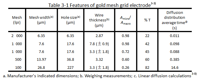
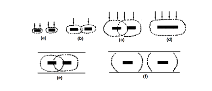
Fig. 3-3 Diffusion characteristics of grid electrode.
The homogeneous geometry of the grid gives a "double feature" in terms of the diffusion of the electroactive material to the electrode, which is manifested in a short time after the potential step to a single wire. As shown in Fig. 3-3-a, the effective electrode area is therefore the microscopic area of the mesh (A micro). After a shorter period of time (depending on the spatial dimensions of the mesh) the diffusion layers overlap each other as in Fig. 3-3-b. Then the electroactive material in the holes in the mesh undergoes completely depleting electrolysis as in Fig. 3-2-C. The arrows indicate the direction of diffusion of the electroactive material, the same as on the flat electrode in Figure 3-2-d. The diffusion is effective for the total two-dimensional area of the mesh or a few geometric (macro) areas (A macro) is effective. The closer the mesh is, the faster the diffusion layers overlap, so in the timed current experiments under semi-infinite diffusion conditions, the apparent electrode area obtained from it 1/2 from the calculation gradually changes from a shorter time micro value to a longer time macro value, and the transition time from A micro to (A macro) is also shown in Table 3-1 Diffusion distribution averaging time for different apertures of the metal mesh The time for the electrode to reach near planar electrode diffusion depends on the hole size shown in Table 3-1.
If the mesh is sufficiently tight with respect to the thin layer of solution shown in Fig. 3-2 (e), the grid electrode can be approximated as a planar electrode after a short period of time in the thin-layer pool word conformation, while the made grid requires a long electrolysis time to reach planar diffusion, as shown in Fig. 3-2 (f). If it is also used in thin layer spectroelectrochemistry, it will inevitably produce exhaustive electrolysis of the electroactive materials in the cavity. In principle, it is inappropriate to deal it by semi-infinite diffusion at this time.
2.2 Mercury grid electrode
Mercury grid electrode is also prepared by electrodepositing thin film of accumulated mercury on Ni, Au-grid substrates3-6) - 3-7). Fig. 3-4 show thin iE curves describing the negative potential limit of different grid electrodes and hanging mercury electrodes (0.1 mol/L HCl, 0.5 mol/L KCl 3-6) ). Since the mercury film slowly dissolves the Au substrate while producing gold amalgam on the electrode surface, the grid electrode must be re-plated daily in order to maintain the maximum hydrogen overvoltage, and one (200 rods/cm) Au grid electrode can withstand 10-30 mercury plating cycles.
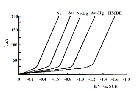
Fig. 3-4 Thin-layer voltammograms describing the negative potential limits of different grid electrodes and mercury grid electrodes.
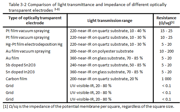
2.3 Comparison of transmittance and impedance of different light transmitting electrodes
The grid electrode is mainly used to compare the optical and electrical parameters of the light transmitting electrode in the light transmitting thin layer spectroelectrochemistry. Table 3-2 shows the comparison of transmittance and impedance of different light transmitting electrodes. It can be seen that the light transmission spectrum range of the grid electrode is larger, and the electrode impedance is lower. The advantage of the metal grid electrode is that it serves as an electrode with very good conductivity, and at the same time has high light permeability, can be bent into different geometric shapes and unlimited spectral range. One of its disadvantages is the non-transmission of metal wires. It hinders the observation of adsorption phenomenon with perpendicular incidence of luminosity. Another disadvantage is the complicated diffusion behavior in spectroelectrochemical experiments in a short time.
2.4 ALS gold and platinum wire gauze working electrode
ALS provides customers with two kinds of gold and platinum mesh electrodes. The gold mesh grid is 100 mesh, and the platinum mesh mesh is 80 mesh, which means the number of holes per square inch (2.54 mm) on the screen, and 50 mesh means that there are 50 holes per square inch (2.54 mm). The higher the number of mesh, there are more holes , and the lower the light transmission rate. 80 mesh platinum wire mesh working electrode light transmission rate is about 50%-55%. The presence of contaminants on the mesh will affect the light transmission rate and electrochemical reaction characteristics.
The cleaning method of metal wire gauze electrode: 1) electrochemical cyclic voltammetric scanning cleaning method in sulfuric acid; 2) ultrasonic cleaning method; 3) if there is no ultrasonic cleaning equipment, you can try to use cotton swab + polishing solution (PK- 3) to clean the metal wire gauze electrode. The method is convenient and quick, and can effectively clean the surface of wire gauze electrode in a short time (it is only useful if it is slightly dirty).
3. Porous glassy carbon electrode and porous metal electrode
Reticulated Vitreous Carbon (RVC) is a glass-like carbon with 97% void volume and porous structure, as shown in Fig. 3-6. RVC can have different porosity, and when cut into thin slices, their light transmission is comparable to that of mesh grid electrodes (for 1.2-0.5 mm thick 40-hole RVC. T = 13-45%), is essentially constant throughout the UV-visible spectrum, and can achieve complete electrolysis of the active material in a very short time because the majority of the solution is inside the porous electrode 3-9). Such electrodes are fragile and require special care during operation. Foam-type metallic materials such as nickel porous metal foams can also be cut into thin slices for use as optically transparent electrodes. The above porous electrodes are prepared for easy light transmission and light range length, which can be adjusted within a certain range by selecting different pore sizes and different thicknesses of materials. Optically transparent electrodes made of porous materials are most suitable for measuring samples with weak light absorption and are also mainly used to form thin layer cells due to their complex diffusion behavior in a short time.
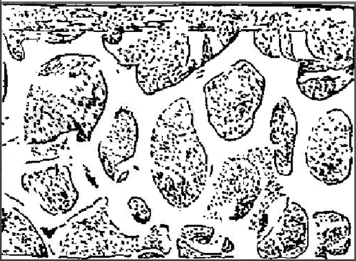
Fig. 3-5 Scanning electron microscope photo of Au-RVC electrode3-10)
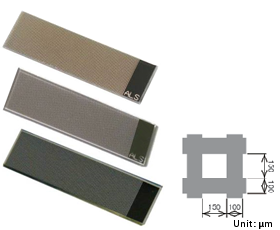
Fig. 3-6 ALS thin film grid electrode.
4. Thin film grid electrodes (Pt, Au, C)
Finally, we introduce a modified thin film optically transparent electrode - thin-film grid electrode. In the previous article, we introduced that ITO optically transparent electrodes can be used for spectroelectrochemical flow cell measurement. But from the point of view of optical properties; the light transmittance of ITO optically transparent electrode in the visible light region is as good as 70%-85%, but it absorbs ultraviolet light and cannot be used for spectrum measurement in the ultraviolet range. Although Au and Pt film electrodes based on quartz glass can be used for measurements outside the ultraviolet range, the lower light transmittance of the electrodes, about 10%.
In order to improve the light transmittance of the metal film electrode, a grid electrode of Au, Pt and C materials suitable for spectroelectrochemical flow cells was fabricated using lithography technology (Fig. 3-6). ALS provides customers with grid electrodes of three electrode materials, which are mainly used in spectroelectrochemical flow cells. When using, simply clip the grid electrode into the flow cell and place the flow cell into the SEC2020 spectrometer system, and spectroelectrochemical flow cell measurements can be easily performed.
Click to watch this lecture
References:
3-1) T. P. De Angelis, P.W. Hurst, A. M. Yacynyh, H. B. Maek, W. R. Heineman and J. S. Mattson, Anal. Chem., Vol.49, No.9, 1395-1398 (1977).
3-2) R. W. Murry, W. R. Heineman and G. W. O'Dom, Anal, Chem., Vol. 39, No.13,1666-1668 (1967).
3-3) M. Petek, T. E. Neal and R. W. Murray, Anal, Chem., Vol. 43, No.8, 1069-1074 (1971)。
3-4) W. J. Blaedel and S. L. Boyer, Anal. Chem., Vol.45, No.2 , 258-263(1973).
3-5) D. Lexa, J. M. Saveant and J. Zickler, J. Am. Chem. Soc., Vol.99, No.8, 2786-2790 (1977).
3-6) M. L. Meyer, T. P. De Angelis and W. R. Heineman, Anal, Chem., Vol.49, No.4, 602-606 (1977).
3-7) W.R. Heineman, T. P. Deangelis and J. F. Goeiz, Anal. Chem., Vol.47, No.8, 1364-1369 (1975).
3-8) T. Kuwana and W. R. Heineman, Acc. Chem. Res. Vol. 9, No.7, 241-248 (1976).
3-9) J. W. Sorrels and H. D. Dewald, Anal, Chem., Vol. 62, No.15, 1640-1643 (1990).
3-10) D. E. Hobart, V. E. Norvell, P. G.Varlashkin, H. E. Hellwege and J. R. Peterson, Anal. Chem., Vol. 55, No.9, 1634-1637(1983).

