Section 2: Cyclic voltammetry (electrochemical measurement technique)
2-1 Summary
Cyclic voltammetry (CV), one of the electrochemical measurement techniques, is a very popular measurement method for the initial evaluation of heterogeneous redox reactions. This chapter will introduces chemists to the CV measurement method.
Cyclic voltammetry (CV) is becoming more and more popular as an effective measurement method in a wide range of chemistry as a means of studying redox states. The electrode potential at which drugs, metal ions, complexes, proteins or other compounds are oxidized or reduced can be quickly determined by CV.
In addition, CVs provide information on the stability of the product of the electrode reaction. This information is useful for subsequent experiments such as LCEC, stripping voltammetry, electrolytic polymerization, corrosion, coulometry, etc. CV measurements are the first experiment to be carried out before electrical experiments using methods such as chronoamperometry, chronocoulometry, spectroelectrochemistry 1‚2), etc.
CV quickly became a popular method due to its effectiveness and convenience.
The effectiveness of CV is that it can quickly investigate redox reactivity over a wide potential range. The resulting voltammogram is similar to the spectrum obtained as a result of the energy scan.
An important aspect of the CV is that it can create a new redox species in the first scan and follow the disappearance of that species in subsequent scans. Therefore, CV is a powerful kinetics probe for monitoring reactive species. Since the potential scan rate can be changed, high-speed and low-speed chemical reactions can be investigated. Despite its wide range of applications, CV is not as commonly understood as other analytical methods such as spectroscopy and chromatography.
2-2 Fundamentals of CV
Cyclic voltammetry (CV) is an electrochemical measurement technique in which an electrode is immersed in a stationary sample solution and the current flowing through it is measured by repeatedly scanning the potential. The potential of the working electrode is controlled against a reference electrode such as a saturated caromel electrode (SCE) or a silver chloride electrode (Ag / AgCl). The control potential is regarded as an excitation signal. The excitation signal of a CV is a linear potential scan in a triangular waveform (see Fig. 2-1).
The excitation signal of the triangular waveform potential changes the direction of the sweep at a point called the switching potential. The excitation signal in Figure 2-1 scans from 0.00 V to -1.00 V in the negative direction with respect to the reference electrode, and then reverses and scans back to the original 0.00 V in the positive direction.
The scan rate, expressed as a gradient, is 20 mV / sec, and the second scan is indicated by the dotted line. The measurement parameters is setting through the software, according to the electrochemical analyzer used.
The cyclic voltamogram is expressed as a current-voltage curve. The current is considered as the response signal to the potential excitation signal. The current-voltage axis is shown in Figure 2-2. Since the potential is proportional to time, the horizontal axis can be regarded as the time axis. This helps to understand the basics of the CV technique. The oxidation and reduction intensities of the electrode are controlled by the applied voltage.
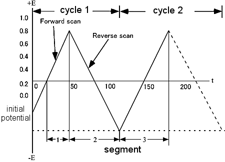
Fig. 2-1 Typical excitation signal of CV.
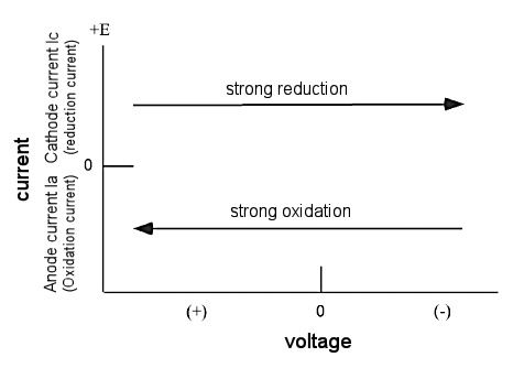
Fig. 2-2 Current-voltage curve of CV.
A potential scan in the negative direction makes the electrode a strong reducing agent. On the other hand, a positive potential scan makes the electrode a strong oxidizer. Figure 2-3 shows a typical cyclic voltammogram. Tin oxide film was used as the working electrode, 0.5 mM Methyl viologen di-cation (MV-2+) was used as the sample, and 0.1 M pH 7.0 phosphate buffer was used as the supporting electrolyte.
The excitation signal used is shown in Fig. 2-1, with a switching potential of -0.92 V. The initial potential is set to 0.00 V.

No electrolysis of MV2+ occurs at this potential. If the potential is made sufficiently negative to reduce MV, a reduction current flows through the electrode process as shown in equation above. The reduction current increases as it progresses from b to d. At d, the MV2+ concentration at the electrode surface is zero (peak d).
Since MV2+ is insufficient on the electrode surface due to reduction to MV+, the reduction current decays with a dependence of t-1/2 because MV2+ is insufficient at the electrode surface due to reduction to MV+. At -0.92 V, the scan direction is reversed and scanned in the positive direction. The MV+ that had been generated near the electrode is now oxidized (next equation), and the oxidation current flows. The oxidation current increases as we move from g to j, and at j, the MV+ concentration at the electrode surface becomes zero (peak j).
The first scan ends when the potential reaches zero. From this voltammogram, the anodic current (ipa), cathodic current (ipc), anodic peak potential (Epa), and cathodic peak potential (Epc) can be obtained. When using electrochemical analyzer, electrochemically important parameters are displayed on the monitor. In the case of an analog measuring device, it is calculated from the voltammogram shown in Fig. 2-3. The standard redox potential is E0 = (Epa + Epc)/2. The difference in peak potentials is (ΔEp = Epa - Epc = 58/n)mV (n: number of electrons transferred per mole molecule).
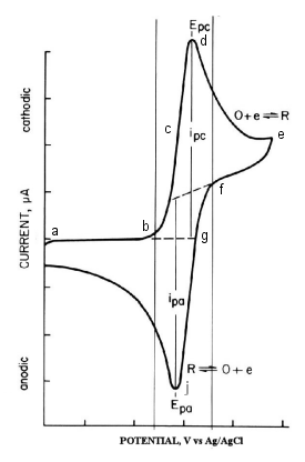
Fig. 2-3 Cyclic voltammogram of 0.5 mM Methyl viologen.
(Scan rate 20 mV/sec, electrode surface area 0.6 cm)
In cyclic voltammetry, a reversible process, the peak current is expressed by the Randles-Sevcik equation.
According to this equation, ip is proportional to the concentration C and proportional to the scan speed v1/2. there are a number of parameters that affect the CV curve. There are many parameters that affect the CV curve. For slow electron transfer reactions it increases &DeltaEp. The electron transfer reaction rate constant can be calculated by examining ΔEp and the scan rate. Note that the uncompensated resistance between the working and reference electrodes increases ΔEp. The effect of uncompensated resistance can be reduced by performing iR compensation.
2-3 About the device
Cyclic voltammetry (CV) is an electrochemical measurement technique that requires a potentiostat, an electrochemical measurement cell, and a PC for control and analysis.
The basic type of potentiostat used for electrochemical measurements is the three-pole type. The potentiostat applies an arbitrary potential between the working and reference electrodes. The working electrode causes the electrolysis of the sample of interest to occur on the electrode. The current required to maintain electrolysis at the working electrode is provided by the counter electrode. In the three-electrode method using a potentiostat, the current is prevented from flowing to the reference electrode.
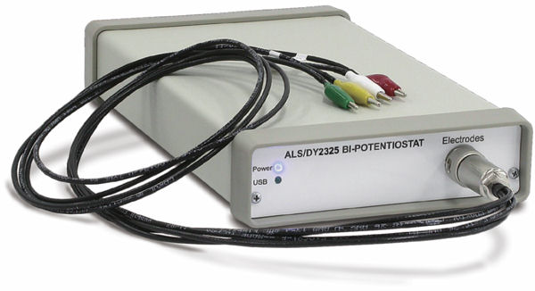
Fig. 2-4 Electrochemical measurement system Model 2325 Bi-Potentiostat.
2-4 Electrochemical measurement cell
The following is a list of basic items needed to perform electrochemical measurements.
- Cell & cap
Prepare a glass cell to hold the sample and a cap to hold the electrode.
In addition, nitrogen gas must be bubbled to remove dissolved oxygen in the sample to maintain an oxygen-free state.
- Reference electrode
Prepare a reference electrode that matches the solvent. A saturated calomel electrode (SCE) or Ag/AgCl electrode is typically used.
In addition, select for organic solvents or alkaline solutions, if required.
Use a salt bridge for the reference electrode to prevent contamination between the reference electrode and the sample.
- Counter electrode
A platinum wire is used as the counter electrode, and it is directly immersed in the sample. Since the peak current is temperature dependent, it is better to use a thermostat or similar device to keep the sample temperature constant.
- Working electrode
Many materials are used for the working electrode, but when investigating the reduction region, the mercury electrode is the best electrode.
Platinum, gold, glassy carbon, graphite, carbon paste, etc. are commonly used as solid electrodes. These electrodes have good properties in the oxidation region.
There is also a voltammetry that uses a dropping mercury electrode (DME) and is called polarography. This electrode continuously drops mercury droplets from the tip of the glass capillary. Hanging mercury drop electrodes (HMDE) are widely used for CV measurements.
A thin layer of mercury is attached to a substrate electrode such as graphite to make a mercury film electrode. Mercury film electrodes are more convenient to use than DME.
Chemically modified electrodes and biosensors are also being studied using CV.
2-5 Conclusion
Cyclic volmethanemetry (CV) measurement, one of the electrochemical measurement techniques, is a popular measuring method for investigating redox states in all fields of chemistry. It can scan a wide potential range to determine the oxidized and reduced species of the sample. This, combined with the ability to vary the time scale and high sensitivity, makes CV measurements the most versatile electrochemical method. However, it is important to note that its features remain within the framework of qualitative or diagnostic use.
For quantitative measurements, as reaction rate and concentration measurements, other methods, such as, potential step method, pulse method, etc., are more suitable. In CV measurement, the reaction rate is often dominated, and care must be taken when determining thermodynamic parameters such as standard redox potential.
2-6 CV measurement
Measurement example of cyclic voltammetry (CV) measurement, which is one of the electrochemical measurement technique.
- Preparation of sample solution: 2 mM K3Fe(CN)6 solution (containing 1 M KNO3 as supporting electrolyte)
1. Add 16.5 mg potassium ferricyanide (special grade) to the beaker.
2. Add 2.53 g potassium nitrate to the same beaker.
3. Add ion-exchange water to dissolve, and transfer to a 25 mL flask for scale-up.
- Electrodes used
1. AUE Gold electrode OD:6mm ID:1.6mm (Cat. No.002014)
2. RE-1B Reference electrode (Ag/AgCl) (Cat. No.012167)
3. Platinum counter electrode 23cm (Cat. No.012961)
- Equipments used
1. CHI600E Potentiostat/Galvanostat
2. CS-3A Cell Stand Ver.1.1 (Cat. No.012779)
- Measurement parameters
The parameters are as follows, changing only the scan speed to 0.5, 0.25, 0.1, 0.05, and 0.25 for the measurement.
Monitor and display the potential-current data points on the screen.
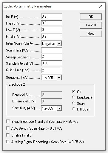
Fig. 2-5 Measurement parameters.
Cyclic Voltamogram example using ALS Model 600D Electrochemical Analyzer.
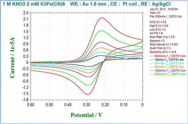
Fig. 2-6 Example of cyclic voltammogram by ALS model 600D electrochemical analyzer (overlay display).
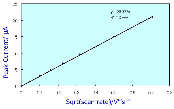
Fig. 2-7 Dependence of peak current value on scan speed.
In the case of a diffusion-dominated reversible process, according to5) ip = 2.69x10⁵n3/2AD1/2Cv1/2, the peak current value is proportional to the square root of the scan speed, as shown in Fig. 2-7. From the slope of this line, the diffusion coefficient and other parameters can also be obtained.
Reference:
1) Bard,A.J. and Faulkner,L,R.,Elecrochemical Methods (wiley,New York,1980).
2) Kissinger,P.T. and Heineman.W.R., Ends.,Laboratory Techniques in Electroanalytical Chemistry (Marcel Dekker, New York, 1984.
3) Howell.J., Currnet Separations,Vol.8(1987)2.
4) Kissinger,P.T.,Currnet Separations,Vol.6(1985)65.
5) R.S. Nicholson, I.Shain, Anal.Chem.,36,706(1964).

