Part 11: Hydrodynamic Modulation (HDM)
The current response to an applied potential is determined by many factors. The two most important points are the electron transfer rate and the mass transfer rate from the bulk solution to the working electrode surface. There are three ways in which mass transfer can occur.
- Diffusion - Molecular motion due to concentration gradient
- Electrophoresis - Molecular motion due to potential gradient
- Convection - Molecular motion caused by disturbances such as vibration and agitation
In order to obtain quantitative data from voltammetry experiments, it is important that the mass transfer mode is defined in a form that is easy to analyze mathematically. The addition of a fully dissociated electrolyte, electrophoretic effects can be ignored in all voltammetry experiments. The mass transfer mode of the system consists mainly of diffusion and convection. In many voltammetry experiments, convection is eliminated by not stirring the solution and preventing external vibrations (such conditions are only maintained for a relatively short period of time).
Voltammetric method using static solution state includes cyclic voltammetry (CV), chronocoulometry, pulse and square wave techniques. In addition to the experimental difficulties of maintaining convection-free conditions, diffusion dominated experiments are limited by the lack of methods to change the mass transfer rate.
In the hydrodynamic technique, molecules are transported to the electrode surface in a well-defined manner. That is, by stirring the solution, or by pumping the solution through the flow cell as in liquid chromatography/electrochemical detection systems. The most widely adopted method is to rotate the electrode using a rotating disk electrode. Hydrodynamic techniques have many advantages over static solution techniques due to the increased mass transfer rate into and out of the electrode surface. As a result of the balancing of mass transfer and electron transfer, faster mass transfer rates allow steady state to be reached sooner, and steady state is maintained when the scan rate is slow enough (usually about 20 mV/s or less).
One advantage of steady-state voltammetry is that at a given potential, the current is not dependent of both scan direction and time. In this case, the voltammogram is characterized by a sigmoid curve. Fast mass transfer increases the sensitivity of quantitative analysis, and rotating disk electrodes are often used in the precipitation step of stripping experiments. The limiting current (mass transfer current) for reversible processesis given by the Levich equation.
C = concentration (mole/cm3), D = diffusion coefficient (cm2/s), ω = 2πf ((rotation speed/rps), ν = dynamic viscosity
Therefore, the plot il vs. ω1/2 for a reversible process is a straight line (Levich plot).
In this case, reversible means that fast electron transfer is required relative to the mass transfer rate, i.e., the redox reaction may shift from reversible to quasi-reversible when the rotational speed increases. This is shown by the deviation from linearity in the Levich plot. The electron transfer rate is calculated from the kinetic current when the rotational speed is extrapolated to infinity.
This kinetic current is obtained from the intercept of the inverse Levich plot (l/il vs.1/ω1/2). This method is often used in corrosion and battery research. It is also used to measure the electron transfer rate through a polymer film coated on the electrode surface.

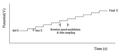
Fig. 11-1 HDM applied potential waveform.
Hydrodynamic modulation (HDM) is a related technique that changes the rotation frequency in a sinusoidal manner. While il is proportional to ω1/2, ω1/2 itself also changes. The alternating current is processed using the usual data processing methods. That is, after passing through the filter, data is processed after rectification or phase discrimination detection.
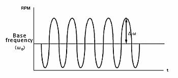
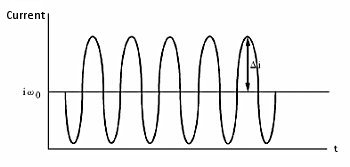
According to the Levich equation, il = Kω1/2, where ω1/2 = ω01/2 + Δω1/2sinσt; (ω0 is the center rotation speed and is modulated by a sine waveform with frequency σ, amplitude Δω1/2 , see Fig. 11-2), the AC output is shown in Fig. 11-3, and Δi is given by the following equation:


Fig. 11-2 Modulation of rotational speed using HDM technique.

Fig. 11-3 AC Output of HDM.

