Experimental Guide for Synchronized Spectroelectrochemical Measurements (Using SEC2020 + Model 3325)
Spectroelectrochemical measurements can be understood as the synchronized measurement of spectroscopic changes in a specimen solution near an electrode during an electrochemical reaction. This method can simultaneously obtain information on electrochemical variables (current, charge and potential) and spectroscopic variables (transmittance, absorption, reflection) in the electrode process experiment, which is helpful for further research on the mechanism and intermediate analysis of the electrode process and the characterization of the product.
In general, spectroelectrochemical measurements require the use of a potentiostat and a spectrometer at the same time, but are characterized by the use of a special working electrode, the “optically transparent electrode”, and a special measuring cell, the “thin-layer spectroelectrochemical cell”. The spectroelectrochemical synchronization of the measurement is furthermore achieved by triggering the spectrometer (hardware/software) with a potentiostat (hardware/software). In this section, Model 3325 Bi-Pootentiostat and SEC2020 Spectrometer system are used to introduce how to set up the trigger control (hardware/software) to perform the spectroelectrochemical synchonized measurement.
The Model3325 Bi-Potentiostat and SEC2020 Spectrometer system are used here as an example of how to set up the trigger control (hardware/software) to achieve synchronized spectroelectrochemical measurement.

When performing trigger control, the trigger connection line (trigger-input) attached to the SEC2020 spectrometer is controlled and connected with the trigger signal output line (trigger-output) of the Model3325 Bi-Potentiostat to perform the trigger control of the spectrometer (control software) for measurement by the potentiostat (control software) and achieve the synchronization of the two measurements. Trigger control is simply divided into two major components. Hardware settings (trigger control connection between Model3325 and SEC2020 devices), and software settings (trigger signal output of Model3325 software, and trigger signal input setting of SEC2020 software). The above picture shows the connections of the systems after the settings are completed.
- I. Set up for Spectroelectrochemical Synchronized Measurement
- II. Trigger cable connection method
- III. Thin-layer measurement cell SEC-C
- IV. Trigger mode setting - SEC020 Spectrometer system and Model 3325
I. Set up for Spectroelectrochemical Synchronized Measurement
The basic configuration and system settings for synchronized spectroelectrochemical measurements using the Model 3325 Bi-Potentiostat (for electrochemical measurements) and the SEC2020 Spectrometer system (for spectrum measurements) is introduced in this section.
The set up for the spectroelectrochemical synchronized measurement consists of three mainly components:
1. Spectrometer (SEC2020 Spectrometer system)
2. Potentiostat (Model3325 Bi-Potentiostat)
3. Spectroelectrochemical reaction cell (SEC-CT Thin Layer Quartz Glass Spectroelectrochemical cell kit (Pt))
Each of the above three components is described below.
1) SEC2020 Spectrometer system
For spectrum measurements, it is a trigger command receiving device.
Different from the usual spectral measurement control, when performing spectroelectrochemical synchronized measurement, the spectrometer needs to be connected to the external trigger control signal input cable (Signal-in cable) to accept the trigger control of the external device. The following lists the components used in the spectrometer system.

Fig. 3-1 SEC2020 Spectrometer system components
1) SEC2021 Spectrometer
1a) Spectrometer light inlet protection cover
2) SEC2022 Deuterium halogen light source
2a) Light source outlet protection cover
3) SEC2023 Cuvette holder
4) Fiber collimator
5) SMA905 adaptor for light shielding
6) SEC2024 Platform
7) Trigger/Light source control cable
2) Model 3325 Bi-Potentiostat
For electrochemical measurements, it is a trigger command output device.
When using the Model 3325 Bi-Potentiostat for spectroelectrochemical synchronized measurement control, the remote cable, which is the signal output cable, is required to connect to the signal input cable of the SEC2020 Spectrometer system. This connection is required for the trigger synchronized measurement controlled for both software, input signal for the spectrometer and output signal for the potentiostat.

.")
3) SEC-CT Thin Layer Quartz Glass Spectroelectrochemical cell kit (Pt) and accessories
 and RE-1BP Reference electrode (Ag/AgCl)")
Fig. 3-4 SEC-CT Thin Layer Quartz Glass Spectroelectrochemical cell kit (Pt) and RE-1BP Reference electrode (Ag/AgCl)
013716
(013718)
(011498)
(013703)
(011498)
013613
SEC-CT Thin Layer Quartz Glass Spectroelectrochemical cell kit (Pt)
SEC-CT Thin Layer Quartz Glass cell
SEC-C Pt Gauze working electrode
SEC-C/C05 Pt counter electrode
SEC-C Teflon cap
RE-1BP Reference electrode (Ag/AgCl)
Since the SEC-C Platinum Wire Gauze Working Electrode (011498) has a platinum wire lead with a diameter of 0.5 mm, it is very fragile and easily bent. Do not clamp the alligator clips of the potentiostat directly onto them. To prevent damage to the electrodes, it is recommended to use the (Cat. No. 011840) IC clip for printed electrodes, for the connection between the electrodes and the potentiostat.
II. Cable connection
Trigger cable (SEC2020 Spectrometer system content) and CB-VS Remote cable (Cat. No. 013818, sold separately. It is not included in the content of Model 3325 Bi-Potentiostat.) are required for the connection.
- SEC2020 Spectrometer system
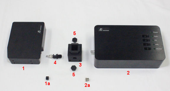

Fig. 2-1 Spectrometer system content.
(1) Spectrometer
(1a) Protector of the SMA 905 from the spectrometer
(2) Light source
(2a) Protector of the SMA 905 from the light source
(3) Cuvette holder
(4) Fiber collimator
(5) SMA905 adaptor for light shielding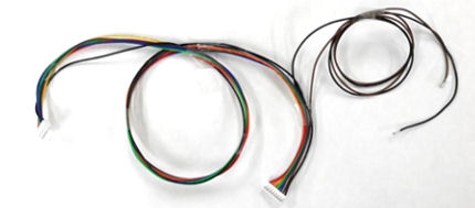
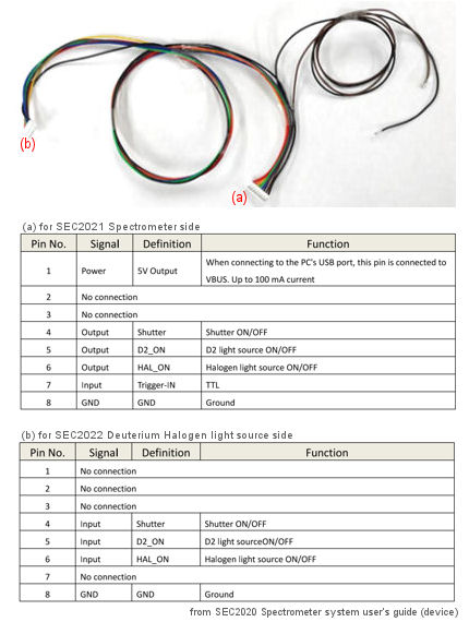
Fig. 2-2 Trigger cable from the content of the SEC2020 Spectrometer system, for the connection of the spectrometer to external device and light source.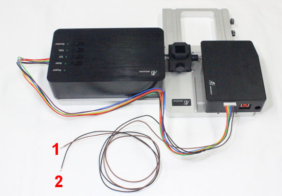
Fig. 2-3 The free two wires (① Brown (Input (Trigger-IN)) and ② Black (Ground (GND)) are for the connection to the potentiostat. For this reason, the connector which has the free wires connected must be connected to the spectrometer.
- Model 3325 Bi-Potentiostat
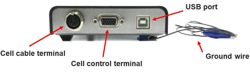
Fig. 2-4 Model 3325 Bi-Potentiostat back panel.
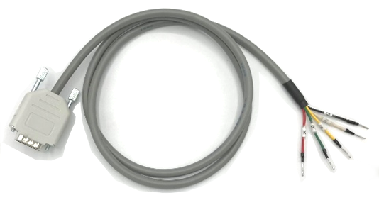
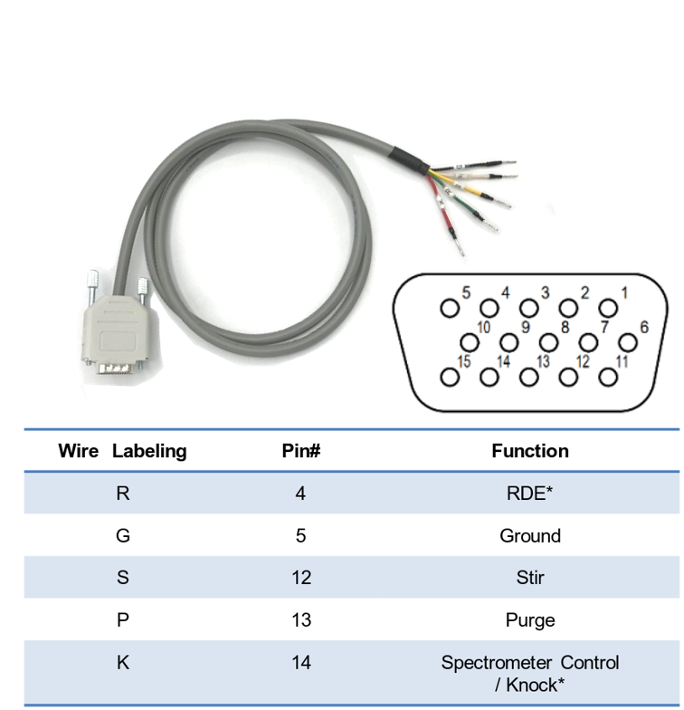
Fig. 2-5 CB-VS Remote cable (Cat. No. 013818) for the connection of the Model 3325 Bi-Potentiostat to SEC2020 Spectrometer system.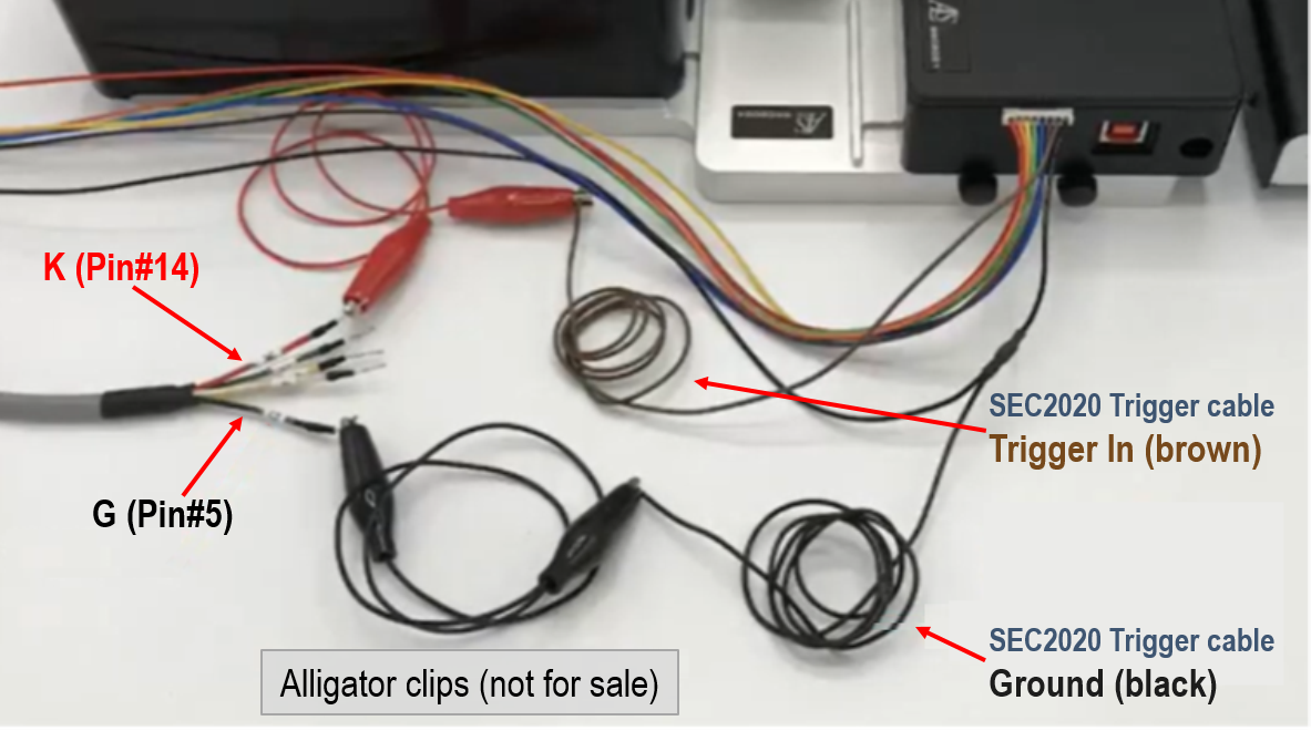
Fig. 2-6 Model 3325 and SEC2020 are connected with CB-VS Remote cable (15 pin) and SEC2020 Trigger cable. Connect G (Pin♯5, Ground) with the SEC2020 Ground (black), and K (Pin♯14, Spectrometer control) with the SEC2020 Trigger In (brown).
Connection of SEC2020 and Model 3325
SEC2020 Spectrometer system and Model 3325 Bi-Potentiostat setting separately in the previous section is connected as shown below.

Fig. 2-7 Connection of the SEC2020 Spectrometer system and Model 3325 Bi-Potentiostat (CB-VS Remote cable, sold separately).
| Model 3325 | Function | SEC2020 Trigger cable |
| K (Pin♯14) | Spectrometer control | Trigger In (brown) |
| G (Pin♯5) | Ground | Ground (black) |
III. SEC-C setting and connection
SEC-CT Thin Layer Quartz Glass Spectroelectrochemical cell kit (Pt) (Cat. No. 013716) is used for the spectroelectrochemical measurement.
For the set up special care for the connection of the working electrode is necessary. In the below connection IC clip for printed electrodes (Cat. No. 011840) is connected to the crocodile clip.
Cell preparation for Spectrometry
Set up of the spectrometer and cuvette is showed below with some "hints".
For the SEC-CT Thin Layer Quartz Glass Spectroelectrochemical cell kit (Pt) (Cat. No. 013716) setting, first set the working electrode and counter electrode into the SEC-C Teflon cap, and then fit to the SEC-CT Thin Layer Quartz Glass cell with the sample to be measured, and last set the reference electrode.
Make sure that the SEC-C Pt Gauze working electrode (Cat. No. 011498) is clean. If not, polish with 0.05 um polishing alumina (Cat. No. 012620) by soft touch using cotton swab, and rinse with distilled water.
For the spectrum measurement, when taking the reference and dark spectrum, do not forget to save both spectrum. The saved spectrum can be used for the subsequent measurement.
After take and save the reference and dark spectrum, SEC2020 Spectrometer system is ready for the target sample measurement.
 Fig. 3-1 For absorbance measurement, as a measurement sample, 2 mM potassium ferrocyanide/1 M KNO3 aqueous solution is used for the reference spectrum.
For the differential absorption spectrum measurement, the spectrum of the sample before measurement is taking as a reference spectrum.
Setting of the cell cable
It is not recommended to clip the SEC-C Pt Gauze working electrode directly, because the connection wire is very thin and it will bend easily.
For the set up below IC clip for printed electrodes (Cat. No. 011840) is used between working electrode and cell cable.
For the connection of the working electrode, take attention to do not clip in the insulated side.
 Fig. 3-2 The connection must be in the exposed wire of SEC-C Pt Gauze working electrode, without the insulation.
 Fig. 3-3 IC clip is used between the crocodile clip of the Model 3325 Bi-Potentiostat cell cable and exposed wire from the SEC-C Pt Gauze working electrode.
Trigger mode setting - SEC020 Spectrometer system and Model 3325
The SEC2020 Spectrometer system supports "trigger mode". The external TTL signal applied to the spectrometer's I/O port controls data acquisition of the spectrometer.
SEC Spectra (SEC2020 Spectrometer system)
Enable trigger mode
To use trigger function, the instrumetn must be set to trigger mode. Prepare a spectrum such as Spectrum or Absorbance measuments in advance.
Select Trigger Settings from the Settings menu.

Fig. 4.1 Select Trigger Settings from the Settings menu.
The Trigger Settings window shows:

Fig. 4-2 Setting Trigger Mode
➀ Check the selection (serial Number)
➁ Select the trigger mode:
SW Level Trigger: Starts/Stops software measurement by TTL signal.
SW Continuous Trigger: Starts software measurement with TTL signal. To stop it, manually stop the software.
➂ Click Enable cicon to active the trigger mode setting.
➃ Click OK icon to exit the screen.
The specttrum acquisition mode is now the trigger mode.
At this time, the signal on the spectrum screen stops and the data acquisition is stopped. The external TTL signal applied to the I/O port of the spectromenter is at "Low level" and the spectrometer is in standby mode.
Note: If data acquisition does not stop after switching to trigger mode, confirm the TTL signal applied to the I/O port os the software settings, as dara acquisition starts when the TTL signal goes to "High level".
You can check the current mode status from Spectrum List -- Mode:. The Fig. 4-3 shows the state set for SW Continuous Trigger mode.

Fig. 4-3 Spectrum List -- Mode: SW Continuous Trigger
Trigger Off (Normal Mode)
To return from trigger mode to normal mode (trigger off), select Triger Settings from Settings menu and set according to the following procedure.
➀ Check the selection (serial Number).
➁ Select the trigger mode:
Trigger Off: Releases from the trigger state.
➂ Click Enable icon to activate the changing of the mode.
➃ Click OK icon to exit the screen.
At this time, the signal on the sspectrum screen moves and data is acquired.
You can check the current mode status fromSpectrum List -- Mode:. The Fig. 4-4 shows the state set for Trigger Off (normal) mode.

Fig. 4-4 Spectrum List -- Mode: Trigger Off
Model 3325 Bi-Potentiostat
The Spectrometer is controlled using the output from Pin#14 of the cell control terminal on the back of the instrument showed at Fig. 2-7, CB-VS Remote cable connection.
Select Other from the Control menu, this command is used to control the spectrometer when performing spectroelectrochemical measurements. It works with CV, LSV, and i-t techniques.
, Other controls (right)")
Fig. 4-5 Toolbar (left), Other controls (right)
At this time, the output from K (Pin#14, Spectrometer control) is still High level. OCPT measurement is performed to set the output from K (Pin#14) to Low level. Since the purpose is to switch to the Low level, the run time is shortened as shown in Fig. 4.6, and the other parameters are set to the default values. When the measurement ends, the output from K (Pin#14) becomes Low level. The trigger output setting for the Model 3325 software is complete.

Fig. 4-6 Model 3325 OCPT parameters screen
※ It is possible to change the output to Low level by selecting a technique other than OCPT measurement, but it is not recommended.
Spectrometer control
When a measurement is executed with On is selected, the TTL signal output is at a High level (5 V) during the measurement and at a Low level (0 V) during all other times.
The output of Pin#14 is High level (5 V) in the initial state. When the measurement (OCPT is recommended) is performed with Spectrometer control turned on, the output state of Pin#14 switches to Low level (0 V). Thereafter, the TTL signal is output at High level (5 V) during measurement and at Low level (0 V) except during measurement.~
Once turned On, it will remain in the Spectrometer Control On state as long as power is supplied to the device. Reset Spectrometer Control to its initial state by disconnecting the USB cable from the device or by turning off the PC.
Note:
1. Please also refer to the instruction manuals for the SEC2020 Spectrometer system and CB-VS remote cable (15 pin).
2. If you turn on the Model 3325 before connecting the trigger/light source control cable, it will not operate properly. Please turn on the power after completing the device setting.
Spectroelectrochemical measurement in trigger mode
After setting the SEC2020 Spectrometer system and Model 3325 Bi-Potentiostat, by starting electrochemical measurement from the Model 3325 software, the spectral signal on the SEC Spectra software screen starts to movie in conjunction and the time course of absorbance is recorded according to the conditions set.
Caution: Do not change the measurement screen od conditions during measurement.

Fig. 4-7 Cyclic voltammogram and absorbance during synchronizing measurement.
When set to "SW Level Trigger", absorbance measurement will stop automatically when the maeasurement of Model 3325 is completed. On the other hand, when "SW Continuous Trigger" is set, absorbance measurement will be stopped manually by the SEC Spectra software.
After stoppig the measurement, to save the recording results, click on save icon in "Strip Chart" window. For "Time Sequence" measurement, the recorded results are saved in a preset folder.