Trigger mode setting - SEC020 Spectrometer system and Model 3325
The SEC2020 Spectrometer system supports "trigger mode". The external TTL signal applied to the spectrometer's I/O port controls data acquisition of the spectrometer.
SEC Spectra (SEC2020 Spectrometer system)
Enable trigger mode
To use trigger function, the instrumetn must be set to trigger mode. Prepare a spectrum such as Spectrum or Absorbance measuments in advance.
Select Trigger Settings from the Settings menu.

Fig. 4.1 Select Trigger Settings from the Settings menu.
The Trigger Settings window shows:
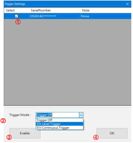
Fig. 4-2 Setting Trigger Mode
➀ Check the selection (serial Number)
➁ Select the trigger mode:
SW Level Trigger: Starts/Stops software measurement by TTL signal.
SW Continuous Trigger: Starts software measurement with TTL signal. To stop it, manually stop the software.
➂ Click Enable cicon to active the trigger mode setting.
➃ Click OK icon to exit the screen.
The specttrum acquisition mode is now the trigger mode.
At this time, the signal on the spectrum screen stops and the data acquisition is stopped. The external TTL signal applied to the I/O port of the spectromenter is at "Low level" and the spectrometer is in standby mode.
Note: If data acquisition does not stop after switching to trigger mode, confirm the TTL signal applied to the I/O port os the software settings, as dara acquisition starts when the TTL signal goes to "High level".
You can check the current mode status from Spectrum List -- Mode:. The Fig. 4-3 shows the state set for SW Continuous Trigger mode.
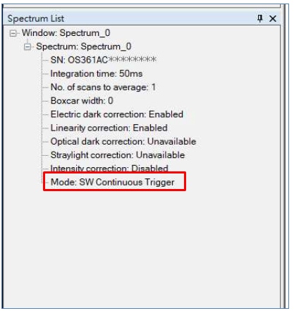
Fig. 4-3 Spectrum List -- Mode: SW Continuous Trigger
Trigger Off (Normal Mode)
To return from trigger mode to normal mode (trigger off), select Triger Settings from Settings menu and set according to the following procedure.
➀ Check the selection (serial Number).
➁ Select the trigger mode:
Trigger Off: Releases from the trigger state.
➂ Click Enable icon to activate the changing of the mode.
➃ Click OK icon to exit the screen.
At this time, the signal on the sspectrum screen moves and data is acquired.
You can check the current mode status fromSpectrum List -- Mode:. The Fig. 4-4 shows the state set for Trigger Off (normal) mode.
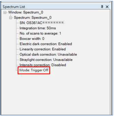
Fig. 4-4 Spectrum List -- Mode: Trigger Off
Model 3325 Bi-Potentiostat
The Spectrometer is controlled using the output from Pin#14 of the cell control terminal on the back of the instrument showed at Fig. 2-7, CB-VS Remote cable connection.
Select Other from the Control menu, this command is used to control the spectrometer when performing spectroelectrochemical measurements. It works with CV, LSV, and i-t techniques.
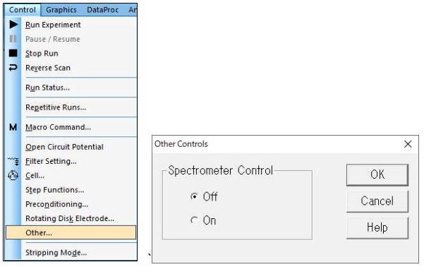
Fig. 4-5 Toolbar (left), Other controls (right)
At this time, the output from K (Pin#14, Spectrometer control) is still High level. OCPT measurement is performed to set the output from K (Pin#14) to Low level. Since the purpose is to switch to the Low level, the run time is shortened as shown in Fig. 4.6, and the other parameters are set to the default values. When the measurement ends, the output from K (Pin#14) becomes Low level. The trigger output setting for the Model 3325 software is complete.
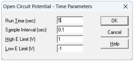
Fig. 4-6 Model 3325 OCPT parameters screen
※ It is possible to change the output to Low level by selecting a technique other than OCPT measurement, but it is not recommended.
Spectrometer control
When a measurement is executed with On is selected, the TTL signal output is at a High level (5 V) during the measurement and at a Low level (0 V) during all other times.
The output of Pin#14 is High level (5 V) in the initial state. When the measurement (OCPT is recommended) is performed with Spectrometer control turned on, the output state of Pin#14 switches to Low level (0 V). Thereafter, the TTL signal is output at High level (5 V) during measurement and at Low level (0 V) except during measurement.~
Once turned On, it will remain in the Spectrometer Control On state as long as power is supplied to the device. Reset Spectrometer Control to its initial state by disconnecting the USB cable from the device or by turning off the PC.
Note:
1. Please also refer to the instruction manuals for the SEC2020 Spectrometer system and CB-VS remote cable (15 pin).
2. If you turn on the Model 3325 before connecting the trigger/light source control cable, it will not operate properly. Please turn on the power after completing the device setting.
Spectroelectrochemical measurement in trigger mode
After setting the SEC2020 Spectrometer system and Model 3325 Bi-Potentiostat, by starting electrochemical measurement from the Model 3325 software, the spectral signal on the SEC Spectra software screen starts to movie in conjunction and the time course of absorbance is recorded according to the conditions set.
Caution: Do not change the measurement screen od conditions during measurement.
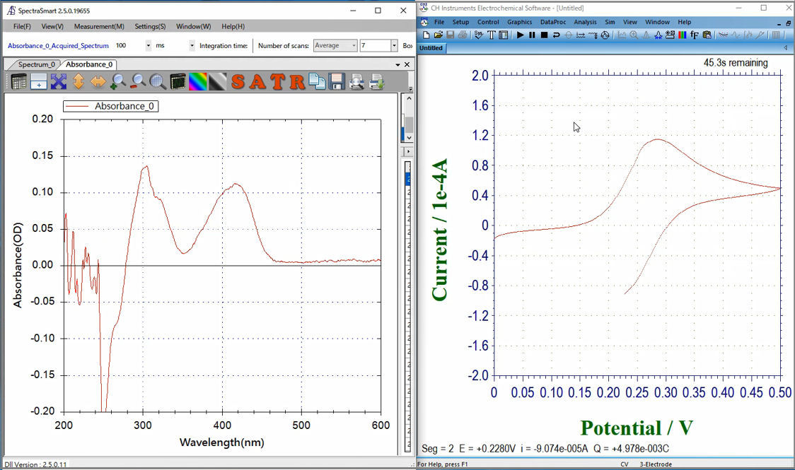
Fig. 4-7 Cyclic voltammogram and absorbance during synchronizing measurement.
When set to "SW Level Trigger", absorbance measurement will stop automatically when the maeasurement of Model 3325 is completed. On the other hand, when "SW Continuous Trigger" is set, absorbance measurement will be stopped manually by the SEC Spectra software.
After stoppig the measurement, to save the recording results, click on save icon in "Strip Chart" window. For "Time Sequence" measurement, the recorded results are saved in a preset folder.

