Connecting other potentiostat
- CH Instruments
- Gamry
Remote connection
The RRDE-3A rotator speed and purge can be controlled by CH Instruments, Inc. Electrochemical Analyzer.
Rotation speed control
Link the CHI and RRDE-3A devices with a banana jack to wire cable. Contact CH Instruments, Inc. to purchase the cable.
| ALS/CHI device | RRDE-3A device | 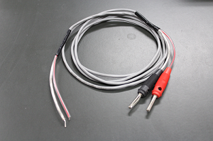 |
| RDE | IN | |
| GND | GND (next to IN) |
Purge control
Link the CHI and RRDE-3A devices with an optional cable. Contact CH Instruments, Inc. to purchase the cable.
| ALS/CHI device | RRDE-3A device | 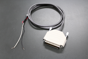 |
|
| Cell Control | White | Purge | |
| Black | GND (next to Purge) | ||
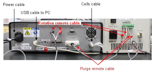
Once all cables connected, you should get this similar configuration:
Cell Connections
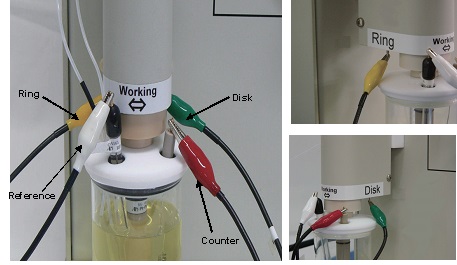
The reference electrode and counter electrode lead wires extend from the potentiostat. The connectors are press-on type. Simply push the connector over the corresponding pin in the electrode to make the connection. Alligator clips are color coded to the electrode it attaches. The ring electrode and the disk electrode connector are located under the motor shaft assembly.
| Wire color | Electrode |
| Green | Disk |
| White | Reference |
| Red | Counter |
| Yellow | Ring |
| Black | Not used |
Gamry potentiostats can be used in BiPotentiostat configuration for the purpose of rotating Ring-Disk electrode experiments. Special cables and scripts are required to synchronize the data acquisition of the potentiostats. In this configuration one potentiostat is the Master and the other is the Serf. The Master will connect to the Disk electrode and the Serf will connect to the Ring electrode.
Editing scripts
For RRDE-3A , 1V corresponds to 1,000 rpm, but the Interface 1000TM is set up with the ratio 0.5V for 1,000 rpm. Therefore we have to edit the Interface 1000TM script from the Inteface 1000TM framework software. To do that, follow this procedure:
- 1- Open the file "classElectrode.exp"
Location:
Win 7, Win 8.1, Win 10:
C:\ProgramData\GamryInstruments\Framework\Scripts\
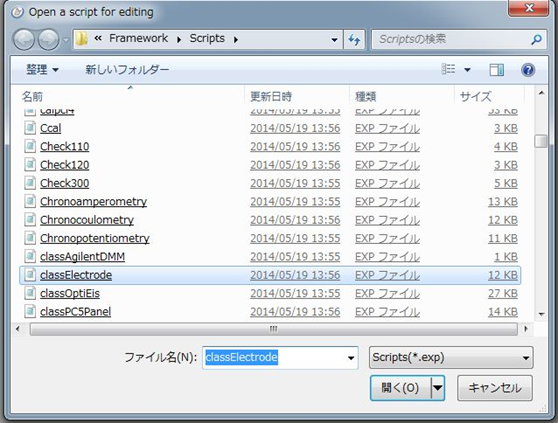
- 2- Rewrite the script as below
Before editing After editing 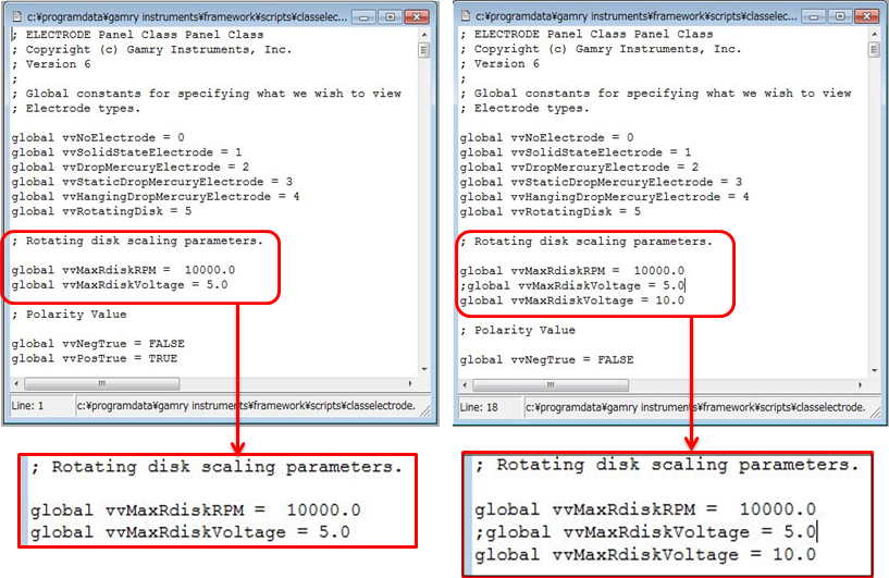
Place a semicolon ";" at the beginning of the line:
global vvMaxRdiskVoltage= 5.0
And add this line:
global vvMaxRdiskVoltage= 10.0
Connecting the Potentiostats
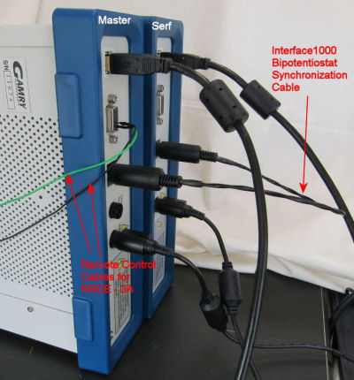
In order to synchronize the Disk scan with the Ring data acquisition, an interconnection is required between the two potentiostats. For this, use Interface 1000TM Bipotentiostat Synchronization Cable, the Gamry standard Master-Serf cable (985-000132 One Master and One Serf) for the connection between Master Interface 1000TM and Serf Interface 1000TM. The Master end of the cable has the identification by a large M on the DIN connector.
Cell Connections
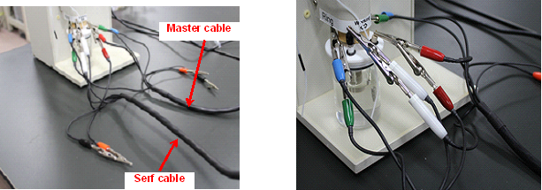
Two standard Gamry Cell Cables are be used to connect to the Cell to the Gamry Potentiostats. There are many wires! Be certain that unwanted interconnections are not made accidentally!
The single Reference Electrode should be connected to BOTH of the White, Reference Electrode pin jack sockets. The single Counter Electrode should be connected to BOTH of the Red, Counter Electrode banana plugs. Banana-to-Alligator or Pin Jack-to-Alligator adapters may be useful here.
The Blue (Working Sense) and Green (Working) leads of the Master potentiostat should be connected to the disk electrode of the RRDE-3A.
The Blue (Working Sense) and Green (Working) leads of the Serf potentiostat should be connected to the ring electrode of the RRDE-3A.
The Counter Sense (Orange) leads of both Gamry Potentiostats should be left disconnected. They are not used.
The Ground wire ("Floating" ground) or the Ground "jack of the Disk Potentiostat may be connected together to provide better noise rejection. The Ground wire and Grounding jack of the Ring Potentiostat must both remain unconnected to any other ground or cell lead.
Remote connection
The current version of Gamry Interface 1000TM series and Gamry Reference 600+ can remotely control the RRDE-3A rotation. Just link the I/O port pin 1 to the IN of the RRDE-3A remote terminal port and the the I/O port pin 2 to the GND of the RRDE-3A remote terminal port.
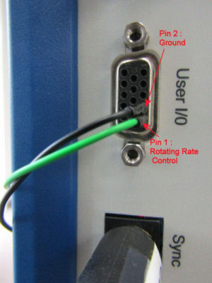
For more information, please contact Gamry.

