4. Rotating ring disk electrode (RRDE) measurement

4.1. Feature for rotating ring disk electrode (RRDE)
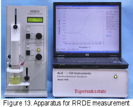
RRDE electrode, composed of ring and disk electrodes, is used for RRDE-3A, as shown in Fig.12. The electrode rotation is controlled by RRDE-3A, and both potentials (ED and ER), from ring and disk electrode, are independently controlled by a common reference electrode and counter electrode. The currents are recorded by a dual potentiostat (700C series electrochemical analyzer).
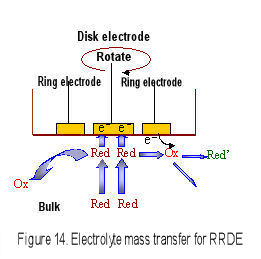
When the RRDE electrode is rotated, the convection occurs near the electrode surface, therefore the diffusion layer thickness is constant and the diffusion limited current is observed. This feature is the same to RDE (Levich equation is used for reversible system). The advantage for RRDE is that the electrolytic product in disk electrode is transported to the ring electrode by centrifugal force and is detected in ring electrode. The electrochemical reaction mechanism in disk electrode is analyzed in more detail.
4.2. RRDE collection efficiency calculation and measurement using reversible system
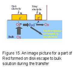
In order to perform quantitative RRDE measurement, it is necessary to understand the electrolytic species transport situation from disk electrode to ring electrode. The typical parameter is Collection Efficiency N.
If the below reactions occur in disk and ring electrodes, the RED species formed ion the disk electrode are oxidized at the ring electrode, which potential has been set to the Red oxidation potential and can be detected as a ring current.
However, a part of RED species generated on the disk electrode may escape to the bulk during transport from the disk electrode to the ring electrode (Fig.15), and the |iD| > |iR| relation can be found. The collection efficiency is defined as a ratio of the absolute value of ring current to disk current (Eq. 6).
- Disk electrode: Ox + e- → Red (reduction)
- Ring electrode: Red - e- → Ox (Oxidation)
- Collection efficiency N = |iR|/|iD| Eq.6
The collection efficiency is a constant determined only by relative configuration and size of both the electrodes and can be calculated using the theoretical equations shown below.
- N = 1 - F(α/β) + β2/3[1 - F(α)] - (1 + α + β)2/3 {1 - F[(α/β)(1 + α + β)]} Eq.7
- α = (r2/r1)3 - 1 Eq.8
- β = (r3/r1)3 - (r2/r1)3 Eq.9
- F(θ) = [31/2/(4π)]ln[(1 + θ1/3)/(1 + θ)] + [3/(2π)] arctan[(2θ1/3 - 1)/31/2] + 1/4 Eq.10
r1 is the radius of a disk electrode, r2 and r3 are the inside and outside radius of a ring electrode, respectively. If r1 = 0.2 cm, r2 = 0.25 cm and r3 = 0.35 cm are used, the calculated collection efficiency is 0.424.
Because an exact electrode surface is uneven, the real collection efficiency is hardly to be coincidence to the theoretical calculation value. In generally, reversible systems such as [Fe(CN)6]4−/[Fe(CN)6]3−, hydroquinone/benzoquinone, ferrocene0/+ , Br−/Br3−and so on are used for RRDE electrode collection efficiency measurement.
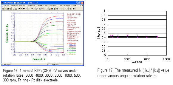
Let's see an example for collection efficiency measurement. A Pt ring-Pt disk electrode (r1 = 0.2 cm, r2 = 0.25 cm, r3 = 0.35 cm) was used for RRDE measurement. The RRDE electrode was dipped into 2 mmol/L K3[Fe(CN)6] in 0.1 mol/L KNO3 solution and rotated under a rotation rate (e.g. ω = 300, 500,……, 5000 rpm). Disk potential ED was scanned from 0.6 V to -0.2 V vs. Ag/AgCl at scan rate 10 mV/s, ring potential ER was fixed to 0.6 V (the reduced product [Fe(CN)6]4- can be oxidized at this potential), and the current-potential voltammograms were recorded during the electrode rotation. Fig.16 shows the RRDE measurement. The ratio of |iR-L| / |iD-L| is almost constant under various ω. The average of collection efficiency N is 0.422, this value is quite near to the calculated N value (0.424).
4.3 Oxygen reduction measurement using Pt ring-GC disk RRDE electrode
Pt ring (ID = 5 mm, OD = 7 mm)- GC disk (D = 4 mm) RRDE (polished by alumina and cleaned before use) electrode was set to the RRDE-3A rotator and put into the cell which was equipped with Ag/AgCl reference and Pt counter electrodes. Electrolyte was 1 M NaOH and the saturated oxygen solution was obtained by purging O2 gas for 30 minutes (purge time was controlled by RRDE-3A remote mode). The potential was scanned under static state to understand the proper potential range for the GC disk electrode (potential range changes with the electrode material).
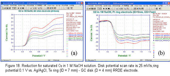
For RRDE measurement, the disk potential scan rate was set to 25 mV/s (depend on experiment, 10, 5 mV/s are also used), the ring potential was set to 0.1 V so that the oxygen reduction product H2O2 formed at disk electrode can be oxidized and detected. The voltammograms were recorded while potential negative scan and electrode rotation. The obtained disk and ring current voltammograms are shown in Fig.18(a) and (b), respectively.

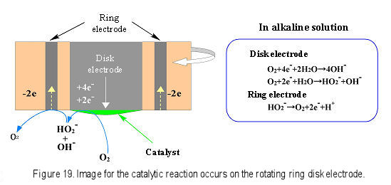
In generally, the oxygen reduction occurred on carbon material in alkaline solution is expressed in above equations. When potential is scanned to negative, the oxygen receives 2 electron (k2) and is changed to HO2-. If the potential is scanned to more negative, furthermore 2 electron reaction (totally 4 electrons) occurs (k3) and OH- is formed, the current increases and the second wave appears. Moreover, the chemical reaction for HO2- disproportionation into O2 and OH- also occurs (k4). Ring potential is set to 0.1 V so that the formed OH- is oxidized completely and detected as ring current.
At -0.5 V disk potential, the disk current of Fig.18(a) increased and the corresponding ring current in Fig.18 (b)also increased. However, when the disk potential was scanned to more negative e.g. -1.0 V, the ring current decreased. This indicated that some of HO2- ion formed on the disk electrode was further reduced to be OH- and caused the ring current decreasing. This means by detection in ring electrode, disk reaction product and reaction mechanism are analyzed. The data in Fig.18 are not so ideal; in reference5) when a Pt ring- pyrolytic graphite (edge plane) disk electrode was used, the second wave 4 electrons reduction proceeded completely, and k1, k2 and k3 were analyzed quantitatively.
In recent years, cathodic catalytic reduction of oxygen relating to fuel cell research has attracted much attention. Platinum or a platinum alloy is often used as electrode catalyst for fuel electrode or oxygen electrode. Research works regarding platinum replacement catalyst are active in order to lower fuel cell development cost6). For example, 4-or 2-electrons oxygen reduction occurred on disk electrode in an alkaline solution. The 2-electrons reduction intermediate HO2- was transported to the ring electrode by rotation and was detected at the ring electrode by oxidation (Fig.19).
Fig. 19 Image for the catalytic reaction occurs on the rotating ring disk electrode.
In reference 6), the oxygen reduction using Ag-W2C catalyst modified on the disk electrode was proved to be 4-electrons reaction by analyzing the ring current. Furthermore, reciprocal current i-1 was plotted to ω-1/2, and Koutecky-Levich plot was obtained. The calculation for slope confirmed that the Ag-W2C was 4-electrons reduction catalyst same to the platinum. Through above RRDE investigation, the platinum substitution catalyst Ag-W2C was estimated to be an outstanding oxygen reduction catalyst.
5. Conclusion
Hydrodynamic voltammetry RDE and RRDE measurements can obtain the constant current by electrode rotation causing convection near the disk surface and controlling the diffusion layer thickness. Electrochemical reaction mechanism for reversible and irreversible systems can be analyzed by changing the rotation rate. Especially, RRDE can be used for studies of wide range applications7-10) such as fuel cell catalyst reaction, metal, alloy dissolution and plating mechanism analysis, electroorganic synthesis, optical reaction, etc. As the hydrodynamic voltammetry RDE and RRDE can help to acquire much electrochemical information, the much more applications in the future are expected.
References
5) C.Paliteiro, A. Hamnett and J.B. Goodenough, J. Electroanal. Chem., 233, 147 (1987).
6) H. Meng, P.K. Shen, Electrochemistry Communication, 8, 588, (2006).
7) T. Ousaka, S. Oyama, T. Ohsaka, Electrochemical Methods, Koudansha, Japan (1989).
8) A. Fujishima and K. Honda, Denki Kagaku (Electrochemistry), 42, 213 (1974).
9) M. Watanabe and H. Uchida, Electrochemistry, 68, 816 (2000).
10) K. Tokuda and T. Ohsaka, Denki Kagaku (Electrochemistry), 61, 193 (1993).
Technical note
Hydrodynamic Voltammetry Measurement Using
Rotating Disk Electrode (RDE) and Rotating Ring Disk Electrode (RRDE)
- Introduction
- Rotating disk electrode (RDE) measurements
- Rotating ring disk electrode (RRDE) measurement

