Basics of Electrochemical and Spectroelectrochemical measurements

ALS provides researchers with a wide range of products for electrochemistry and spectroelectrochemistry applications.
Here, the Basics of Electrochemical and Spectroelectrochemical measurements will be introduced, starting with the preparation of the sample to be used.
After the preparation of the sample, it will be used for electrochemical measurement (cyclic voltammetry) and spectroelectrochemical measurement (observation of absorbance spectrum change during cyclic voltammetry).
- Sample preparation
- Electrochemistry
- Spectroelectrochemistry
Sample preparation
Solutions to be used, in the Fundamental Electrochemical and Spectroelectrochemical measurement, will be prepared and adjusted in this section.
For the electrochemical, spectrochemical and spectroelectrochemical measurement the 2 mM Potassium ferricyanide (K3[Fe(CN)6]) in 1 M Potassium nitrate (KNO3) and 2 mM Potassium ferrocyanide (K4[Fe(CN)6]) in 1 M Potassium nitrate (KNO3) will be used.

The oxidation of ferrocyanide ion to ferricyanide ion is a fast reversible electron transfer reaction at most electrodes. A typical cyclic voltammetry example is the current - potential curve of a solution containing ferrocyanide ion (2 mM potassium ferrocyanide in 1 M potassium nitrate). In this one-electron redox reaction, the ferrocyanide ion Fe(CN)64− is a reductant and the ferricyanide ion Fe(CN)63− is an oxidant.
1 M Potassium nitrate (KNO3)
Potassium nitrate (KNO3), electrochemically inert, is using as a supporting electrolyte, which is required to prevent transport of electroactive species by ion migrating in the electric field gradient.
1 M Potassium nitrate (KNO3) solution will be used to dissolve the salts of Potassium ferrocyanide (K3[Fe(CN)6]) and Potassium ferrocyanide (K4[Fe(CN)6]).
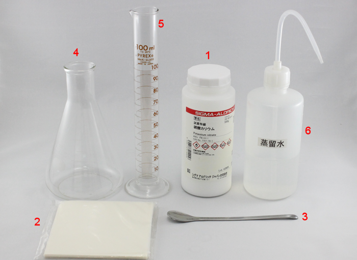
Fig. 1 What you need to prepare:
(1) Potassium nitrate
(2) Weighing paper
(3) Spatula
(4) Beaker 500 mL
(5) Metric cylinder 100 mL
(6) Distilled water
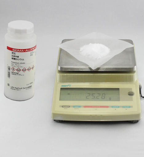
Fig. 2 Weigh the potassium nitrate (1) using folded and creased weighing paper (2) with an electronic balance.
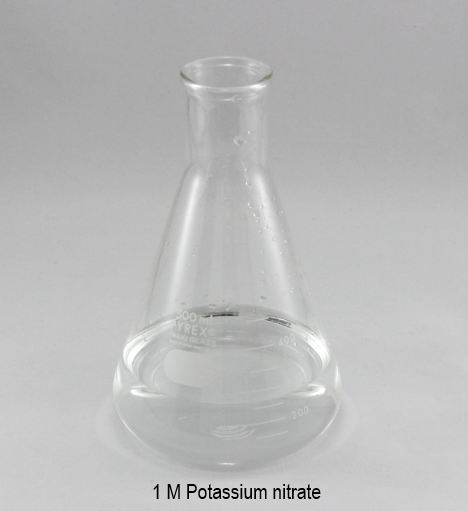
Fig. 3 Transfer the potassium nitrate in to the Beaker 500 mL (4), and dissolve with 250 mL of distilled water (6). Measure the volume of distilled water (6) using a metric cylinder (5).
- Measure the 25.28 g (Fig. 2) of the potassium nitrate (1) using the weighing paper (2). Before set the weight paper (2) in an electronic balance, fold and crease the weighing paper (2). It will prevent that when you add the potassium nitrate (1) using a spatula (3), it spreads on the tray.
- Transfer the measured potassium nitrate to the beaker 500 mL (4) and add the distilled water (6) with a metric cylinder (5) in steps, until complete 250 mL. Using the weighing paper (2) will make easy to transfer the potassium nitrate (1) in to the beaker 500 mL (4) without spreading. Also, using the metric cylinder (5) which has a spout, it will prevent the spilling of the distilled water.
- The solution 1 M Potassium nitrate (Fig. 3) is ready to be used for the preparation of 2 mM Potassium ferrocyanide (K4[Fe(CN)6]) and 2 mM Potassium ferrycyanide (K3[Fe(CN)6]), both in 1 M Potassium nitrate (KNO3).
2 mM K3[Fe(CN)6] and 2 mM K4[Fe(CN)6] in 1 M KNO3
Potassium nitrate will be used as a supporting electrolyte, and 1 M Potassium nitrate solution will be used to dissolve the salts of Potassium ferrocyanide (K4[Fe(CN)6]) and Potassium ferricyanide (K3[Fe(CN)6]).
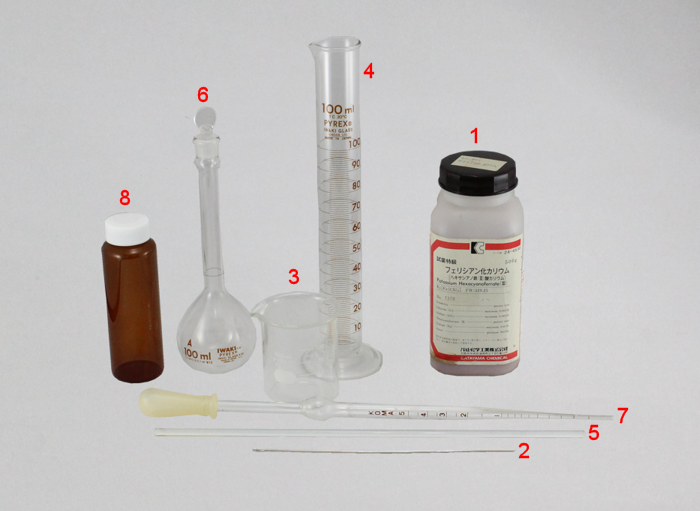
Fig. 4-1 What you need to prepare 2 mM Potassium ferricyanide:
(1) Potassium ferricyanide
(2) Spatula
(3) Beaker 50 mL
(4) Metric cylinder 100 mL
(5) Glass rod (stirring rod)
(6) Volumetric flask
(7) Pipette 5 mL
(8) Shading bottle for storage
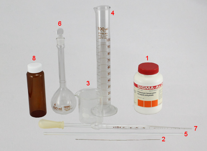
Fig. 4-2 What you need to prepare 2 mM Potassium ferrocyanide:
(1) Potassium ferrocyanide
(2) Spatula
(3) Beaker 50 mL
(4) Metric cylinder 100 mL
(5) Glass rod (stirring rod)
(6) Volumetric flask
(7) Pipette 5 mL
(8) Shading bottle for storager
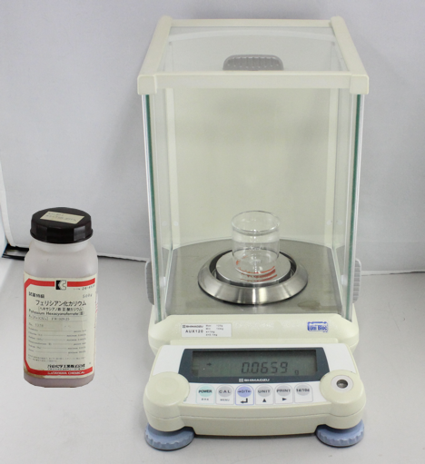
Fig. 5-1 Weigh the potassium ferricyanide (1) using directly the beaker 50 mL (2) with an analytical digital balance.
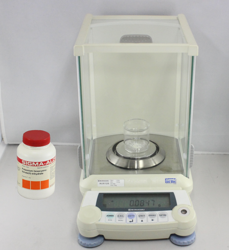
Fig. 5-2 Weigh the potassium ferrocyanide (1) using directly the beaker 50 mL (2) with an analytical digital balance.
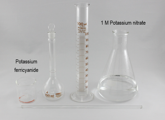
Fig. 6-1 To dissolve the potassium ferricyanide, use the 1 M Potassium nitrate solution prepared in the previous section. The metric cylinder is not required, it was used to know an approximately volume and to prevent the spilling.
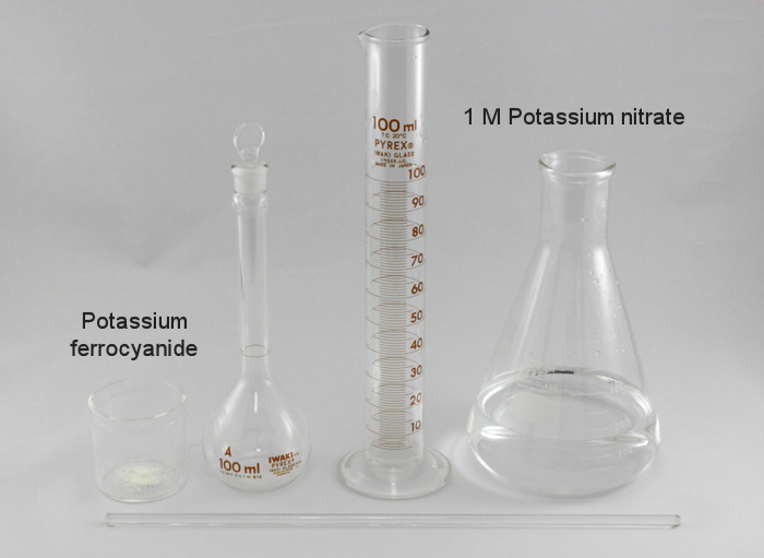
Fig. 6-2 To dissolve the potassium ferrocyanide, use the 1 M Potassium nitrate solution prepared in the previous section. The metric cylinder is not required, it was used to know an approximately volume and to prevent the spilling.
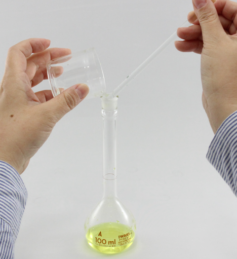
Fig. 7 Add 1 M potassium nitrate solution to the beaker 50 mL (3) with potassium ferricyanide that has been previously weighed. Mix with the glass rod until it dissolves and transfer to the flask draining the solution on the glass rod to prevent the solution from being spilled. Repeat the same process for the potassium ferrocyanide.
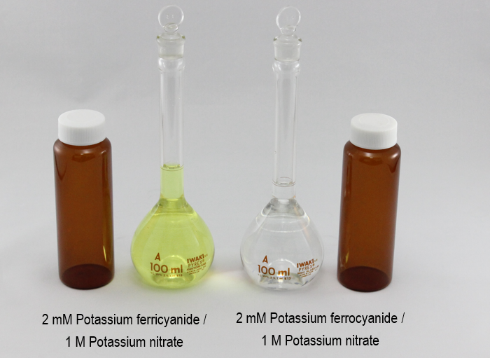
Fig. 8 Transfer the prepared and adjusted solution in to the potassium nitrate in to the Shading bottle for storage (8). Do the same for both solution.
- Measure the 0.0658 g of the potassium ferricyanide and 0.0844 g of the potassium ferrocyanide directly in the beaker 50 mL, using an analytical digital balance (Fig. 5-1 and 5-2).
- Fill the metric cylinder 100 mL with 1 M Potassium nitrate solution prepared in a previous section. The metric cylinder is not required, because the 100 mL volumetric flask will be used and at the end the volume will be adjusted with a pipette. Here, the metric cylinder was used to separate the quantity and to prevent the solution to being spilled.
- Add small quantity of 1 M potassium nitrate solution in the beaker and dissolve the salt mixing with a glass rod.
- Transfer the solution to the flask draining the solution on the glass rod to prevent the solution from being spilled
- Rinse the beaker with 1 M Potassium nitrate and transfer the liquid to the volumetric flask, repeat some times this process.
- Adjust the volume to 100 mL, adding 1 M Potassium nitrate solution with a pipette.
- Transfer the solution from the volumetric flask to the Shading bottle for storage.
Electrochemical measurement
Electrochemical measurement is a method for quantitative and qualitative analysis of ions and dissolved substances in solution, which is artificially controlled by electric potential or current and measures the current and voltage obtained in the process. The measurement system is very simple and consists of a potentiostat to control the voltage and current and an electrolysis cell that serves as the measuring field.
A typical electrochemical measurements are made by an electrochemical measurement system:

(1) Model 2325 Bi-Potentiostat (Cat. No. 013345)
(2) PC
(3) SVC-3 Voltammetry cell (Cat. No. 012669)
(4) GCE Glassy carbon electrode OD:6 mm ID:3 mm (Cat. No. 002012)
(5) RE-1B Reference electrode (Ag/AgCl) (Cat. No. 012167)
Optional items:
(6) RE-PV Preservative vial for reference electrode (Cat. No. 012108), for the storage of the reference electrode
(7) Cell holder for 20 mL vial (Cat. No. 001209), to avoid sample vial turn over
The system consists of an electrochemical measuring device (Model 2325 Bi-Potentiostat), a voltammetry cell (SVC-3 Voltammetry cell) containing an electrolyte (2 mM Potassium ferrocyanide (K4[Fe(CN)6]) in 1 M Potassium nitrate (KNO3) prepared in the previous chapter), and three electrodes (working electrode: causes the desired reaction and obtains a signal; reference electrode: provides the potential (voltage) that is the reference for the system; counter electrode: picks up the current opposite to the working electrode and forms a circuit) connected to the cell cable of the measuring device.
Preparation for measurement
Fill the 2 mM Potassium ferrocyanide (K4[Fe(CN)6]) in 1 M Potassium nitrate (KNO3) into the sample vial.
The sample vial volume is 20 mL, and 5 to 15 mL of the sample is required. Also, the Teflon cap for the SVC-3 Voltammetry cell can fit three electrodes with OD of 6.0 mm.

(green) GCE Glassy carbon electrode OD:6 mm ID:3 mm (Cat. No. 002012)
(white) RE-1B Reference electrode (Ag/AgCl) (Cat. No. 012167)
(red) Platinum counter electrode 5 cm (Cat. No. 002233), it is included as a content for the SVC-3 Voltammetry cell (Cat. No. 012669)
General recommendation for the handling:
• Be careful when the black protective cap is removed from the reference electrode, please follow the instruction from the manual instruction attached to the product.
•After immersed the electrodes to the sample, please check if there is no bubble in the surface of the electrode and at the liquid junction. If there are air bubbles, conduction between the solution inside the electrode and the external solution will not be possible, and an abnormality in the potential will occur.
Model 2325 software parameter setting

For the electrochemical measurement technique, cyclic voltammetry is selected. The cyclic voltammetry is often used as a first method to investigate redox systems and it is a technique for qualitative analysis method of reaction rate and mechanism.
Also, almost of the electrodes, manufactured by ALS Co., Ltd., are inspected by performing cyclic voltammetry measurement using the 2 mM Potassium ferrocyanide (K4[Fe(CN)6]) in 1 M Potassium nitrate (KNO3) (prepared in the previous chapter).
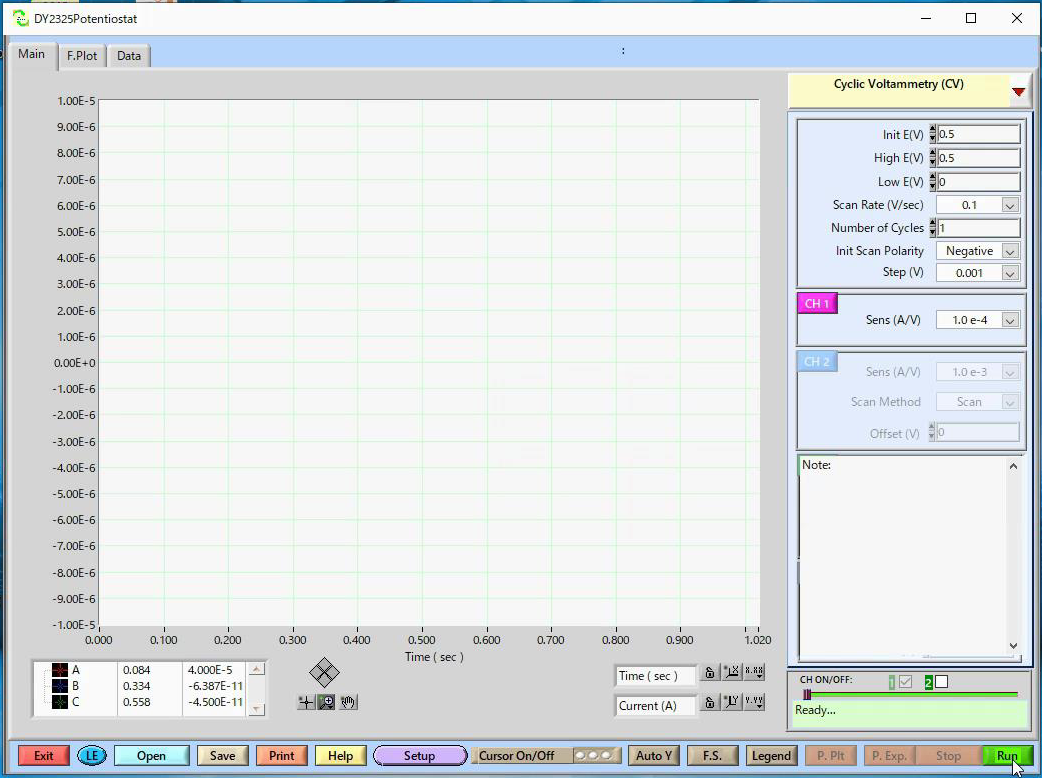
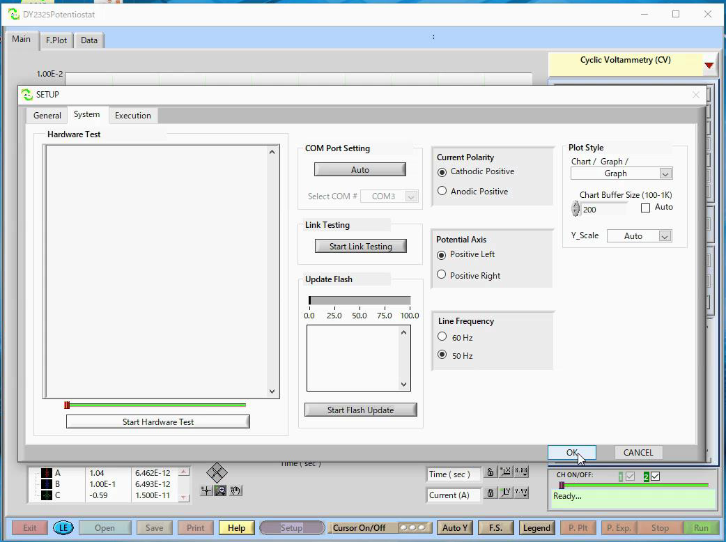
It is ready for the cyclic voltammetry measurement. Press Run to start the scan.
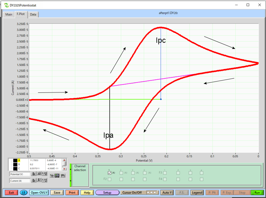
Cyclic voltammogram
Comparative measurement result and recommended storage method for the electrodes are described in this section.
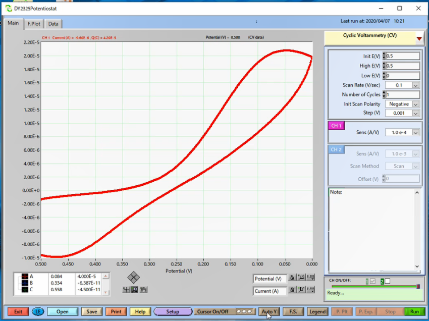
First measurement: it was performed using GCE Glassy carbon electrode OD:6 mm ID:3 mm (Cat. No. 002012) without any treatment. An electrode found in the laboratory, without preventive appropriate storage way.
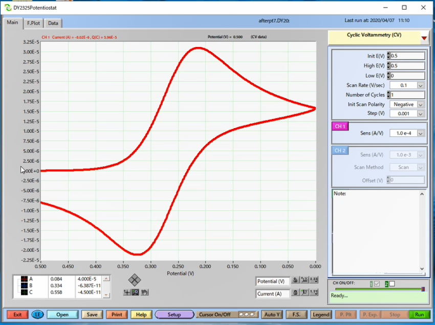
Second measurement: it was performed using the same electrode after polishing with 0.05 µm polishing alumina (Cat. No. 012620) and Alumina polishing pad (Cat. No. 012600).
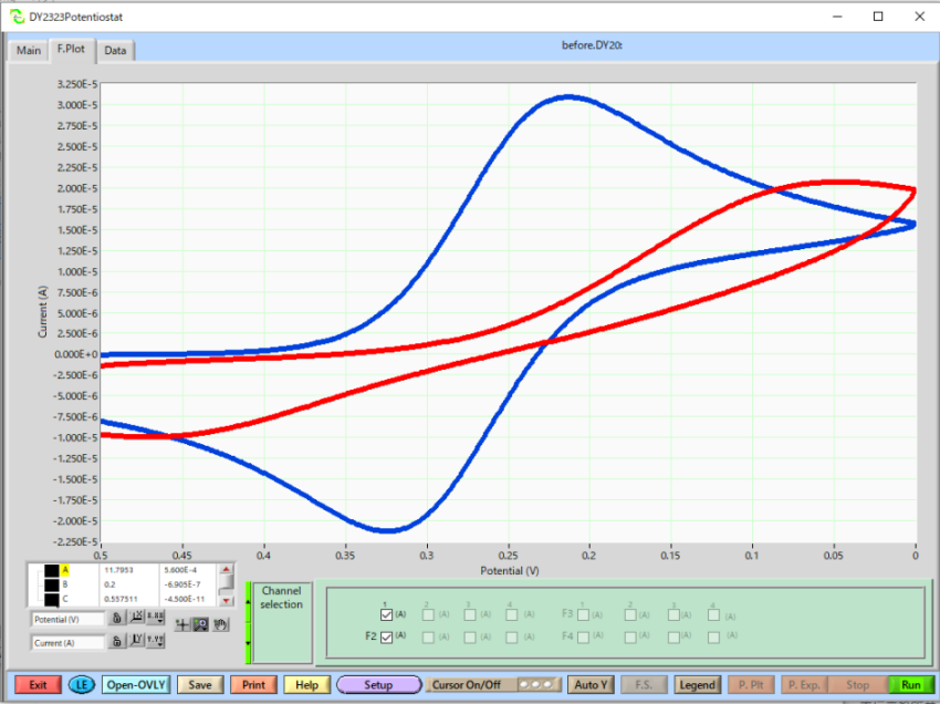
Overlay plot: Red line is before polishing and Blue line is after polishing.
Analyzing cyclic voltammogram
On the surface of the electrode, when the potential is swept in the forward direction, initially only the reductant existed near the electrode, but with an increase in the potential, an oxidation reaction occurred and the reductant decreased and the oxidant increased. The reaction proceeds further, and the reductant disappears on the electrode surface, and the concentration gradient is maximum, and therefore the current is also maximum (Ipc). Sweeping in the opposite direction, essentially the same phenomenon occurs, and the current value becomes the minimum when the concentration gradient becomes maximum (Ipa).
Also, for the data analysis using the Model 2325 Bi-Potentiostat software, it is possible to calculate the diffusion coefficient by the slope of the peak current vs square root of the scan rate plot.
For the detailed theoretic explanation, you can see at Basis of Potentiostat.
Polishing and storage of General Working Electrode
In the case of general polishing, polish with 0.05 µm polishing alumina (Cat. No. 012620) is recommended. However, if regeneration of the electrode surface still does not work, try the 1 µm polishing diamond (Cat. No. 012621).
To ensure that alumina particles adhered to the electrode surface are removed, use a new alumina polishing pad, slightly polish the washed electrode, and then rinse the electrode surface with distilled water and dry.


011132 Working electrode cap
011133 Micro electrode cap
Polishing the surface of the electrode before measurement is strongly recommended to refresh the electrode surface, and to prevent the undesirable measurement result.
Spectroelectrochemical measurement
Spectroelectrochemistry (SEC) is a general term for measurements that combine electrochemical measurement with spectroscopic measurement. The basic principle consists of a measurement system that uses both an electrochemical system and a spectroscopic analysis method, and uses the electrochemical information and the information from spectroscopy to determine the state of the electrode surface and interface.
Specifically, by combining electrochemical analysis and spectroscopic analysis in a spectroelectrochemical cell, it is possible to know the reaction at the electrode surface, the interface between the electrode and the solution, and the electronic state of the molecule at the same time.
Below is the overall schematic diagram of a typical spectroelectrochemical measurement system using transmitting electrodes:

For the system introduced above, the SEC2020 Spectrometer system supports Trigger Mode for synchronized measurement with external device. Depending on the trigger mode, you can control acquisition of spectrometer data with external Input/Output signal. It makes possible to control the spectrometer measurement with external operation of the external devices.
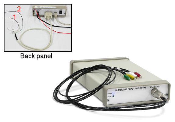
Connection of SEC2020 and Model 2325
For the synchronizing measurement, connect the SEC2020 Spectrometer system and Model 2325 Bi-Potentiostat using the respective cables, Trigger cable (SEC2020 Spectrometer system content, the colorful cable) and Remote cable (included in the content of Model 2325 Bi-Potentiostat).

Connection of the SEC2020 Spectrometer system and Model 2325 Bi-Potentiostat.
| SEC2020 Spectrometer system | Model 2325 Bi-Potentiostat |
| ① Brown (Input (Trigger-IN) |
① V_RDE cable (Voltage output (0 -10 V) that is proportional to RDE rotation speed of 0 – 10000 rpm. 50 ohm output.) |
| ② Black (Ground (GND)) |
② AGND cable (Analog ground of the instrument) |
Trigger setting
1. SEC2020 Spectrometer system (SpectraSmart)
Set the trigger mode in the SEC2021 Spectrometer.
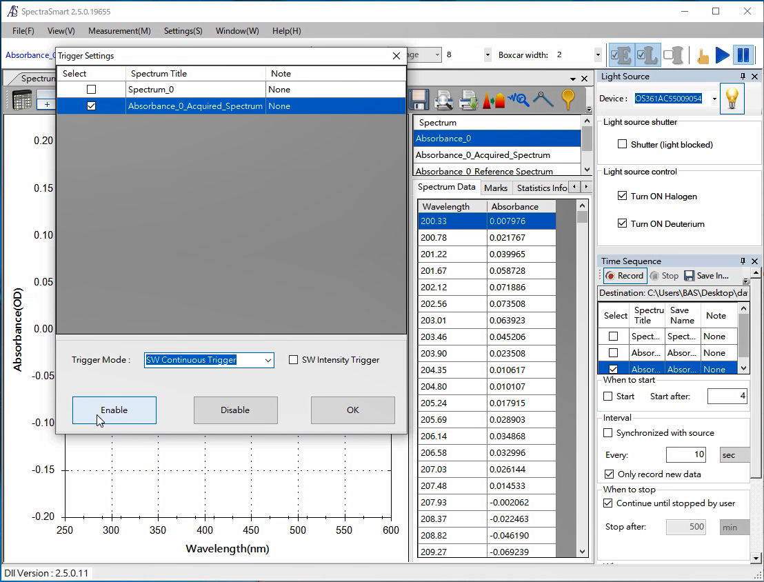
Enabling trigger mode.
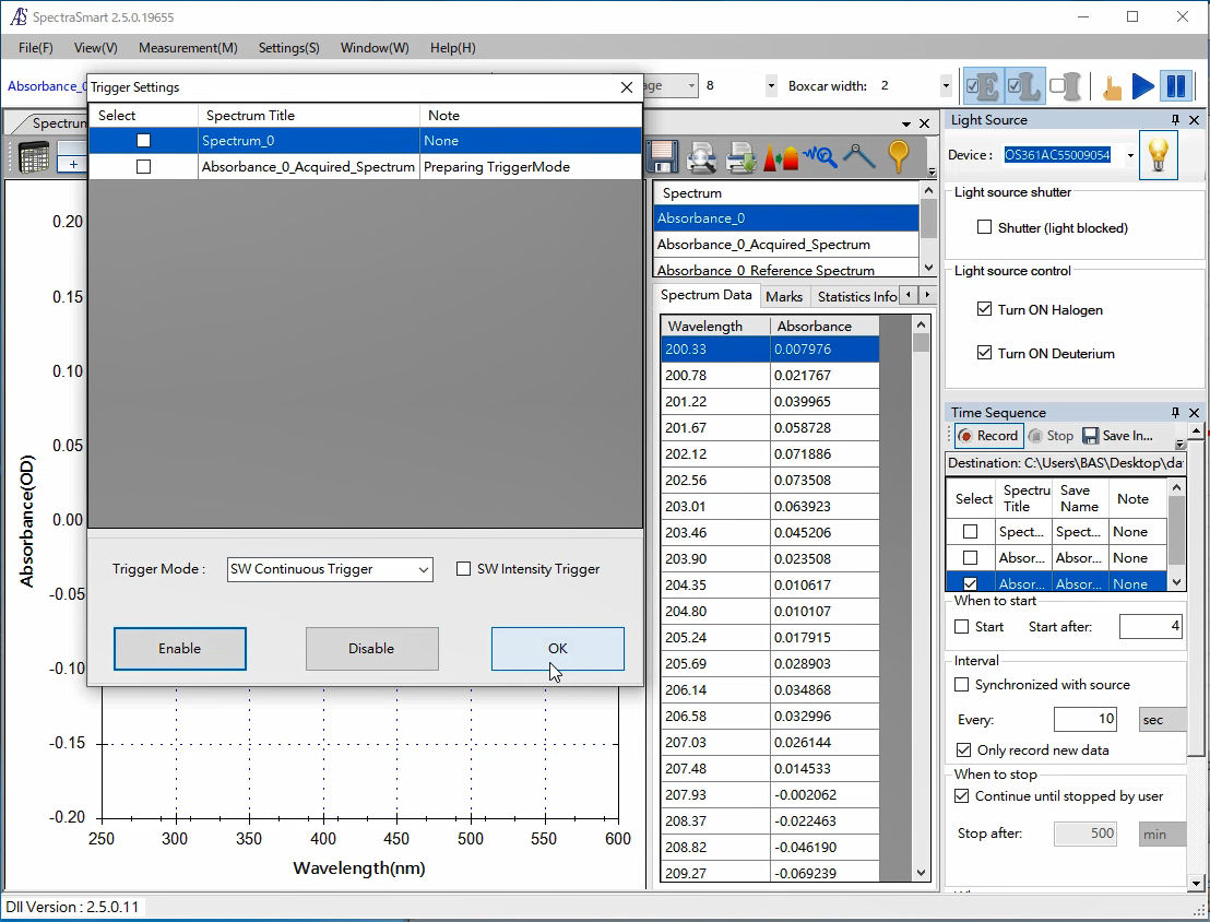
Setting trigger mode.
2. Model 2325 Software
Set the EC parameters and the trigger out of Model 2325 Bi-Potentiostat software.
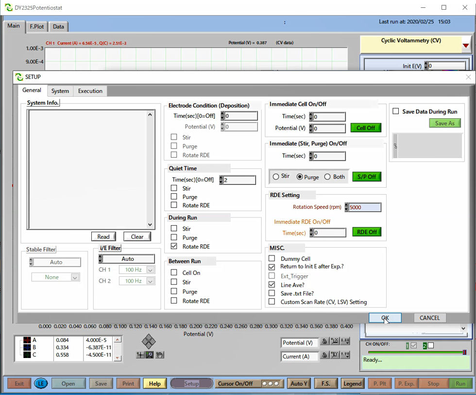
For the synchronized measurement, set the trigger out of Model 2325. In the SETUP window, configure Rotation Speed (pm) to 5000 on the RDE Setting.
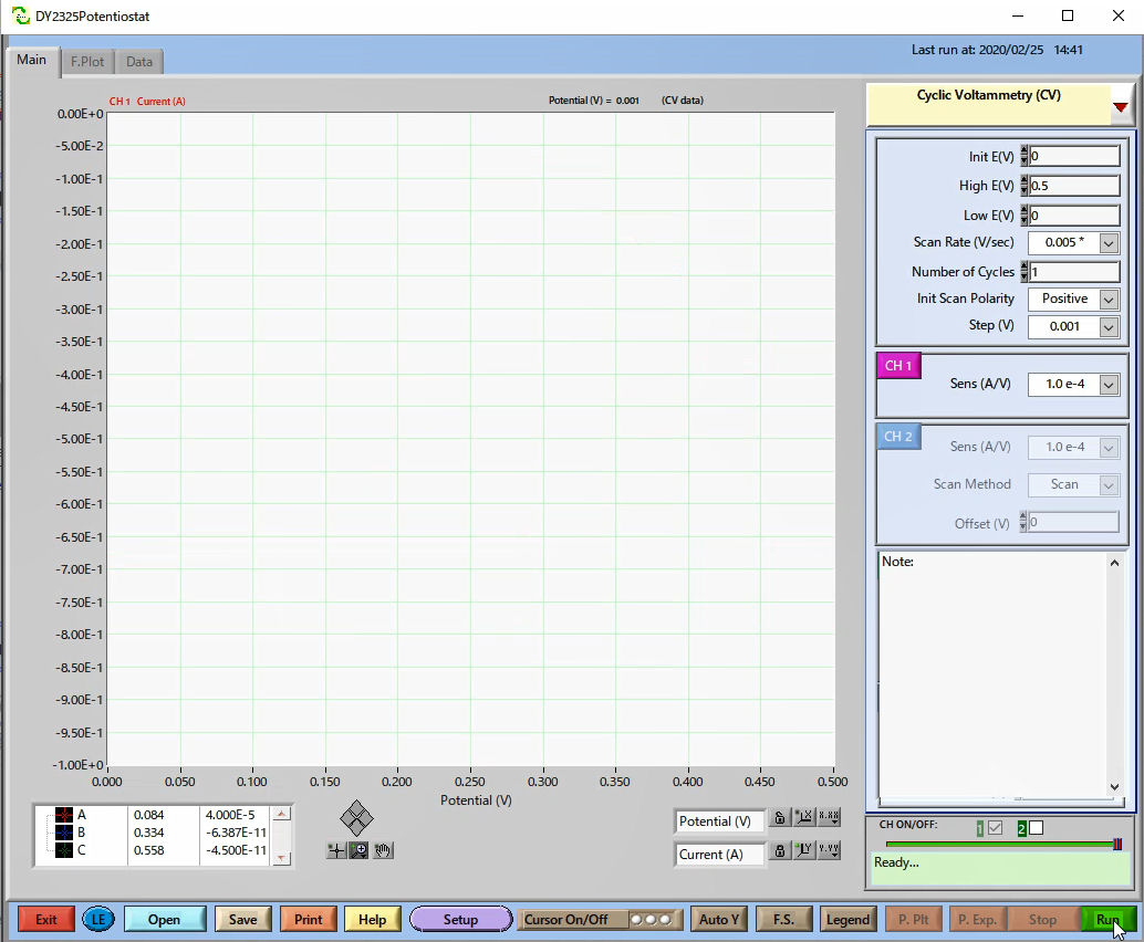
Choose the technique and set the parameters. Here, Cyclic Voltammetry (CV) is selected.
Pressing Run, starts the output signal, and the SEC2020 Spectrometer system receives the signal, starting the measurement.
Note: The SEC2020 Spectrometer does not stop the measurement, and for the record of the measurement data, you need to set the saving way according to the technique you will choose.
Related section:
Synchronized measurement
As an example Interface 1010ETM (Gamry Instruments), Model 2325 Bi-Potentiostat (ALS Co., Ltd.) and Model 760D Bipotentiostat were used.
For detailed explanation, choose one of the potentiostat below:

