This content explains the basics and applications in electrochemistry.
The topics are listed below:
- Part 1: Potentiostat circuit configuration and its features
- Part 2: Bi-Potentiostat
- Part 3: Positive Feedback
- Part 4: The solution resistance and the iR compensation
- Part 5: Electron transfer rate
- Part 6: Redox Potential
- Part 7: Electrochemical Impedance Spectroscopy (EIS)
- Part 8: CV (Cyclic Voltammetry)
Part 2: Bi-Potentiostat
Professor Noriyuki Watanabe
Last time , the potentiostat could be theoretically consisted by the combination of at least two operational amplifiers, the establishment of three fundamental functions (①, the working electrode potential regulation versus the reference electrode, ② measuring the current flowing through the working electrode, ③ no current flowing to the reference electrode), and the points for understanding the function of Op amp (both of input terminals had the same voltage and the input impedance was too large that the current could not flow in or flow out of the Op amp within two input terminals.) were demonstrated.
A typical application example is rotating ring disk electrode (RRDE). In addition, it can be used as the dual working electrodes electrochemical detector (twin-electrode LCEC) as liquid chromatography detectors, and in some cases, it can also be used for liquid-liquid interface voltammetry.

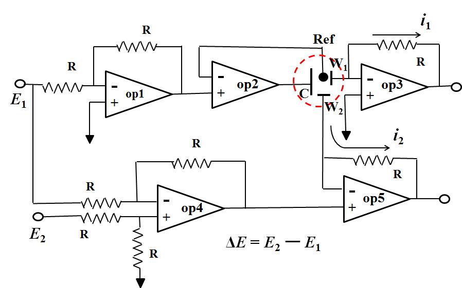
Fig.2 Five Op amps used circuit diagram of bi-potentiostat.
Fig.2 is five Op amps used circuit diagram of bi-potentiostat. The potential of the working electrode 1 (W1) is controlled by Op amp1 and Op amp2 which is same as previously described (only one Op amp used in the previous artical), the regulated potential is E1. Op amp4 is a subtraction circuit which outputs the difference signal between E1 and E2, while becomes the + input terminal of the OP amp5 (signal difference ΔE = E2 - E1). Because the voltages of the + input terminal and the - input terminal are the same (described previously), the potential applied to the working electrode 2 is E2 - E1. E1 is the potential applied to the electrode 1, E2 can completely be selected independently. Therefore, the electrode 2 can be independently controlled.
In this manner, for example of RRDE, it is possible to apply an arbitrary potential independently for the disk electrode and the ring electrode respectively versus the common reference electrode.
Two points in final. One point is a voltage follower. Op Amp 2 is it. Since there is no else connection route to the + terminal except the signal from the former stage (Op amp 1) it has almost no current flow. Since the ─ terminal is the only connection to the reference electrode, there is no current flow over there, whereas the current can flow as the amplifier output (it is connected to the counter electrode C and becomes electrolytic current). This causes the possibility to pass a large current without current flow, that is, impedance conversion is performed. It is used frequently in potentiostat.
Another one point is a subtraction circuit and an addition circuit. In the subtraction circuit, it may be difficult to clearly understand the feature that there is no mutual interference between input signals, for the addition circuit, variables to be added are connected to the same input terminal, so it is easy to convince its effect.
The effective use of addition circuit for the solution resistance compensation positive feedback will be discussed in next edition.

