This content explains the basics and applications in electrochemistry.
The topics are listed below:
- Part 1: Potentiostat circuit configuration and its features
- Part 2: Bi-Potentiostat
- Part 3: Positive Feedback
- Part 4: The solution resistance and the iR compensation
- Part 5: Electron transfer rate
- Part 6: Redox Potential
- Part 7: Electrochemical Impedance Spectroscopy (EIS)
- Part 8: CV (Cyclic Voltammetry)
Part 4: The solution resistance and the iR compensation
Professor Noriyuki Watanabe
In last issue, the positive feedback and the potentiostat might measure the uncompensated solution resistance (Ru) was mentioned, whereas, considering there might be some people want to know how the potentiostat could measure the Ru, therefore, we would like to make it clear in this issue.
The impedance contents of a three electrodes configured cell can be expressed as shown in Fig. 4-1.

Fig. 4-1 Impedance of a three electrodes configured cell.
Zf is the Faraday impedance related to the redox reaction of active species (not considering the diffusion impedance of active species) in solution.
The solution resistance includes the resistance (Rs) between the counter electrode and the reference electrode, and the resistance (Ru) between the reference electrode and the working electrode, which across the reference electrode (usually represented by Rs, Ru respectively). The potentiostat can consider the Rs but can not recognize the Ru (therefore, the potential drop due to the product of the current flowing in the cell and the uncompensated solution resistance i x Ru can’t be controlled by the potentiostat.).
The Zf can be considered as near to infinity at the potential that the redox reaction does not occur, so a substitute equivalent circuit in which the double layer capacity Cdl is in series with the uncompensated solution resistance can be considered.
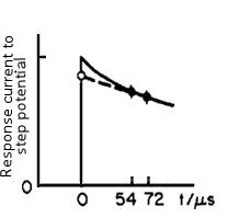
When a small step voltage ΔE (such as 50 mV) is applied to such a circuit, the response current can be described in a scheme which shown in Fig. 4-2.

Fig. 4-2 The time domain of the response current, under a small step voltage applying.
The response current can be expressed by an exponential function with the time constant of RuCdl (the below equation).
When t = 0, the exponential function is 1, so i(0) = ΔE / Ru. That is, if the current value is obtained immediately after the potential applying, as the ΔE is a set value and is known (for example, when set to 50 mV), the value of Ru can be obtained.
The current value at time zero is measured in the manner as shown in Fig. 4-2, that is the current value at two points after the potential step (52 and 72 microseconds in Fig. 4-2) are measured and approximated by extrapolating it to zero time.
When the time constant of the cell (given by Ru × Cdl) is smaller than the rise time of the potentiostat, the error may be large, whatever, such a case means that Ru is small and is almost no need for the iR compensation.
Positive feedback is done using solution resistance Ru obtained in this way. Since Ru is much affected by the position of the reference electrode, it is desirable to place it as near as possible to the working electrode and be careful not to vary for each measurement. Under the minute current of the microelectrode, since the influence is small, the problem of solution resistance is small. In the bulk electrolysis with large current amount, there is a margin in potential setting, so there are relatively less problems. Please note that iR compensation causes instability of the potentiostat, if it is large amount of compensation.

