This content explains the basics and applications in electrochemistry.
The topics are listed below:
- Part 1: Potentiostat circuit configuration and its features
- Part 2: Bi-Potentiostat
- Part 3: Positive Feedback
- Part 4: The solution resistance and the iR compensation
- Part 5: Electron transfer rate
- Part 6: Redox Potential
- Part 7: Electrochemical Impedance Spectroscopy (EIS)
- Part 8: CV (Cyclic Voltammetry)
Part 3: Positive Feedback
Professor Noriyuki Watanabe
In the previous two editions, the potentiostat was talked and the continuation will be presented. The positive feedback is a topic here. This is an optional function which is not always necessary, but you may select to use it, if you need.
When the current flows through the electrolysis cell, a voltage drop proportional to the product of solution resistance and the current value occurs. The potentiostat can not recognize a potential drop proportional to the solution resistance between the working electrode and the reference electrode, while controls the potential of the working electrode.
Since the set up potential is just applied between the working electrode and the reference electrode including this partial of the potential drop, the actual potential applied to working electrode is insufficient by the amount of potential drop.

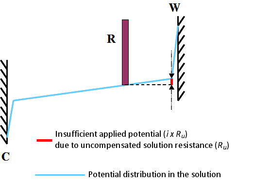
Fig. 3.1 Insufficient applied potential due to uncompensated solution resistance (Ru), W, C, R are the working electrode, the counter electrode and the reference electrode.
This is commonly called uncompensated solution resistance and is marked as Ru. It can be schematically depicted as shown in Fig. 3.1. It shows the state when the current i flows a cell. Subscript u comes from the meaning of either “unkown” or “uncontrollable”.
Even with a potentiostat, such potential drop can not be controlled completely. The only alternative is to deal with incomplete methods with positive feedback as described below.
The unfavorable effect caused by this uncompensated solution resistance is, for example, a peak potential shift and an extra spread of the peak potential width in a CV (Cyclic Voltammetry) measurement.
The deviation of the peak potential causes a difference between the absolute values of the oxidation peak current and the reduction peak current, and the redox potential estimated from the average of the two peak potentials will slightly deviate. Besides, the electron transfer speed calculated from the peak potential width will be slower. For this reason, it is necessary to reduce the effect of uncompensated solution resistance. The method is positive feedback.
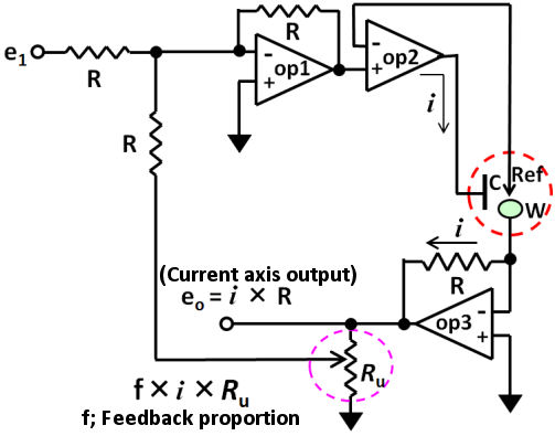
The positive feedback circuit can be configured with three op amps as shown in Fig. 3.2. An additive circuit (op 1) is added to the prototype basic circuit (configured by two op amp) prototype which was mentioned before.
This makes a considerable improvement for the electrochemical measurement. Please do not forget that positive feedback function is not perfect.

Fig. 3.2 The positive feedback circuit for iR compensation.

